Finite Element Analysis (FEA) Articles

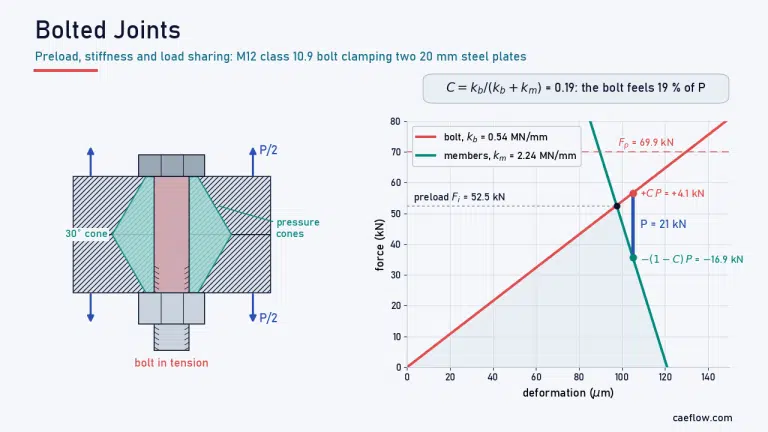
Bolted joint cross-section with 30° pressure cones next to the bolted joint diagram, showing how an M12 class 10.9 bolt shares a 21 kN external load

FEA

Bolted Joints: Interactive Guide to Preload, Stiffness, Fatigue and Shear

Interactive guide to bolted joints: stress area, power screws, the nut factor, joint stiffness, load sharing, bolt fatigue and shear, per Shigley Ch. 8.
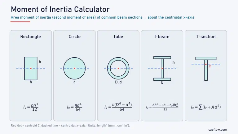
Moment of inertia calculator: area moment of inertia formulas for a rectangle, circle, tube, I-beam and T-section about the centroidal x-axis

FEA

Moment of Inertia Calculator: Area Moment of Inertia of Beam Sections

Free moment of inertia calculator for beam sections: rectangle, I-beam, T, channel, angle, tube or any polygon. Get Ix, Iy, centroid, section modulus and more.
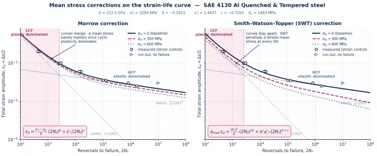
Strain-life curves with Morrow and SWT mean stress corrections for SAE 4130 steel, with measured strain-controlled test data overlaid

FEA

What is Low Cycle Fatigue? Guide for FEA Professionals

What is low cycle fatigue? Plastic strain per cycle, stabilized hysteresis loops, Coffin-Manson life prediction, mean stress relaxation, and the nonlinear FEA workflow that captures it.
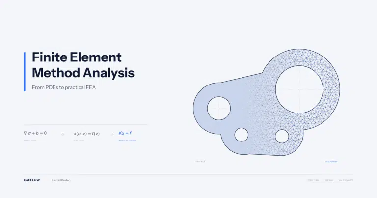
Engineering bracket shown transitioning from smooth solid to triangulated finite element mesh, titled Finite Element Method Analysis

FEA

Finite Element Method Analysis: From PDEs to Practical FEA​

A guide to the finite element method: how FEA turns differential equations into solvable systems, which analysis type to choose, and how to verify results.
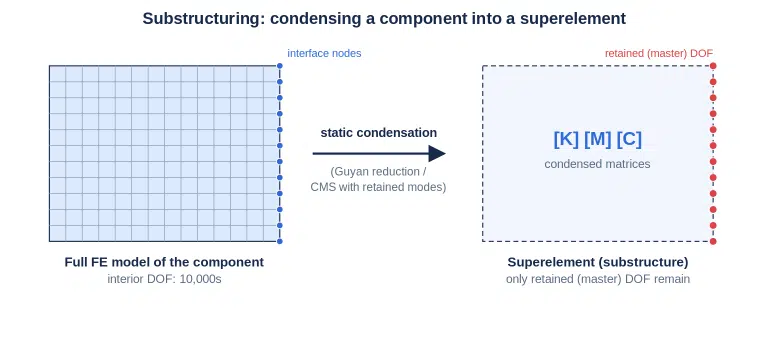
Substructuring in FEA condensing a full finite element model of a component into a superelement with retained master DOF.

FEA

Substructuring in FEA: Superelement & Craig-Bampton Guide

Substructuring condenses linear components into superelements with zero accuracy loss in statics. Learn static condensation, Guyan reduction vs Craig-Bampton CMS, and a proven workflow.
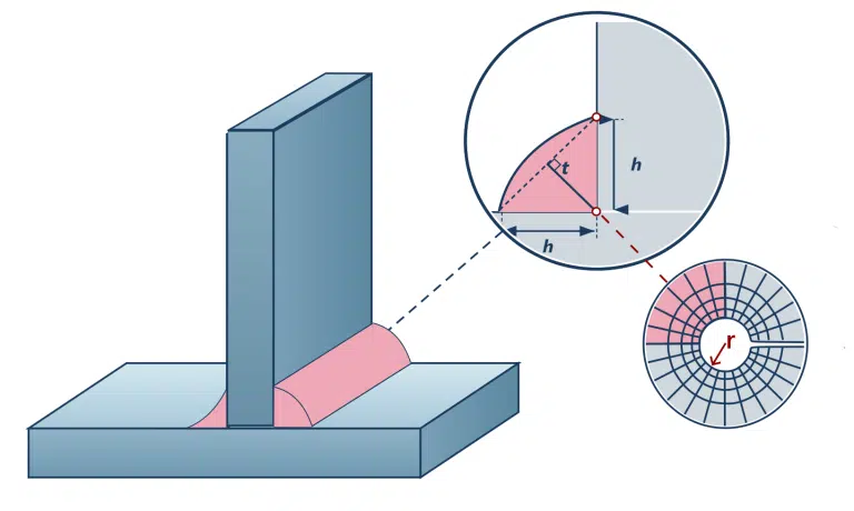
Fillet weld FEA T-joint geometry with weld leg h and throat t dimensions and radial FEA mesh for effective notch stress analysis

FEA

Weld FEA: Finite Element Analysis Guide for Welded Structures

Weld FEA fails at sharp toes, where stress singularities defy mesh refinement. Master shell and solid modeling, stress extraction, mesh sizing, and S-N curve matching.
Three common weld toe defects: undercut, cold lap, and underfill shown in cross-section on fillet welds

FEA

Weld Toe: Definition, Stress Concentration & FEA Modeling Guide

The weld toe is where fatigue cracks initiate in welded structures. Learn to define it, model its stress concentration in FEA, and extend fatigue life.
Fillet weld throat comparison between concave and convex weld bead profiles showing effective throat t and leg size h

FEA

What Is Weld Throat? Calculation, Measurement & AWS Guide

Learn how to calculate weld throat for fillet and butt welds, avoid the common leg-vs-throat error, and apply correct dimensions in FEA stress models.
Side-by-side stress-strain diagrams comparing Neuber's rule and Glinka's rule for FEA plasticity correction. The left graph shows Neuber's rule using equivalent triangular areas, while the right graph shows Glinka's Equivalent Strain Energy Density (ESED) method using the area under the material curve.

FEA

Neuber’s Rule in FEA: Complete Plasticity Correction Guide

Neuber's rule converts pseudo-elastic FEA stress into realistic elastic-plastic results for fatigue analysis. Learn the formula, Neuber vs. Glinka, and step-by-step workflow.
Scroll to Top