Key Takeaways
Weld throat, not leg size, determines load-carrying capacity—for equal-leg fillet welds, throat = 0.707 × leg size
CJP welds have throat equal to plate thickness; PJP welds have throat equal to specified penetration depth (always less than plate thickness)
Minimum throat requirements exist for metallurgical reasons (preventing cracking), not just strength—AWS D1.1 requires 5mm minimum for cyclically loaded structures
Common mistake: Confusing leg size with throat dimension creates a 30% error (1/0.707 ≈ 1.41) that directly scales calculated stresses
- In FEA models, weld stress = Force / (throat × length)—incorrect throat dimensions compromise every downstream calculation
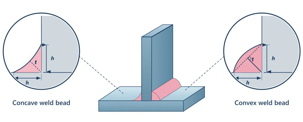
Table of Contents
Introduction
Getting the weld throat dimension wrong in an FEA model doesn’t just affect accuracy — it fundamentally compromises safety factors. Countless structural analyses have revealed cases where engineers specified leg sizes but extracted stresses based on incorrect throat assumptions, leading to non-conservative results or massively over-engineered joints. The weld throat thickness — not the leg size shown on drawings — determines the actual load-carrying cross-section, making accurate throat definition critical to any reliable FEA workflow. This article clarifies the difference between theoretical, actual, and effective weld throat, and connects these concepts directly to practical stress extraction techniques.
What Is Weld Throat and Why It Matters in Structural Analysis?
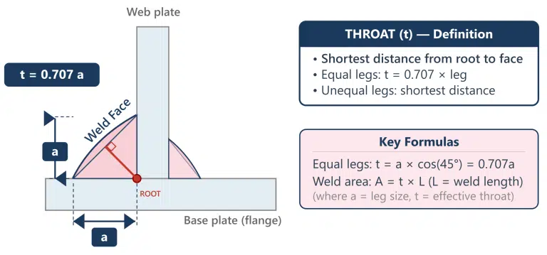
Weld throat is the shortest perpendicular distance from the root of a weld to its face surface, defining the load-carrying cross-section of the joint. For fillet welds, this throat dimension represents the height of the largest inscribed triangle within the weld profile. This critical measurement establishes the effective area used in strength calculations and stress analysis for welded connections.
Why does this matter for FEA professionals? The throat dimension directly controls your calculated stress values. When you extract forces from your model and convert them to weld stresses, you’re dividing by throat area. The stress $\sigma_w$ or $\tau_w$ in a weld throat a for a weld of length l_w and applied force *F* follows the relationship:
$$\sigma_w = \frac{F}{A_w}= \frac{F}{t * l_w} \tag{1}$$
Get the throat wrong, and every downstream calculation inherits that error.
Throat vs. Leg: Critical Geometric Distinctions
Engineers specify leg size on drawings because it’s easily measured during fabrication. However, we analyze throat thickness because it represents the actual load path. For equal-leg fillet welds, the geometric relationship is straightforward: throat = leg × 0.707 (the cosine of 45°). A 6mm leg produces approximately 4.2mm of throat.
⚠️ Common Mistake: Confusing leg size with weld throat dimension when setting up weld stress calculations. This 30% difference (1/0.707 ≈ 1.41) directly scales your calculated stresses—and your safety margins.
For unequal-leg fillets, calculate weld throat as the perpendicular distance from root to the line connecting the weld toes. This requires more careful geometric consideration in your FEA preprocessing.
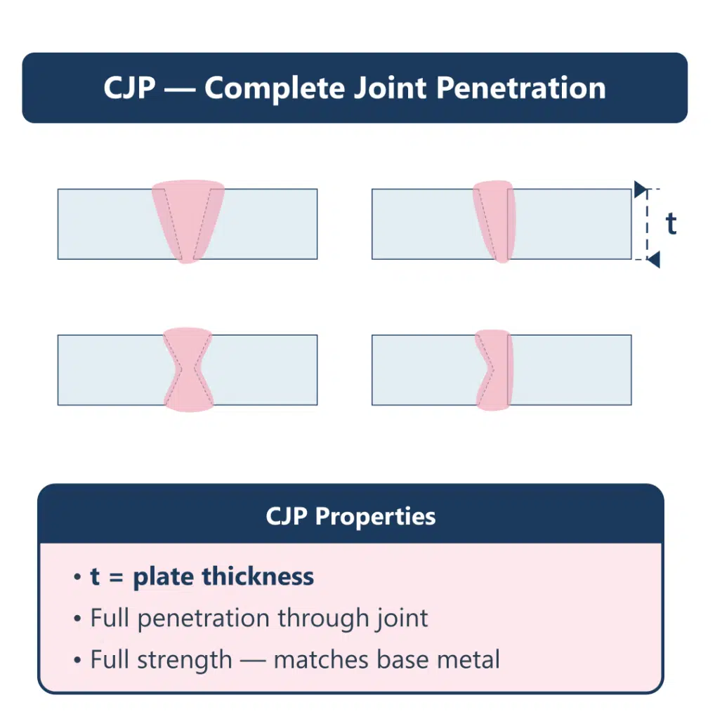
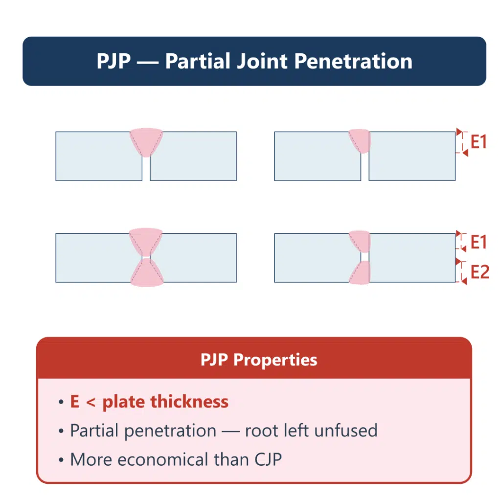
For butt welds: The weld throat definition differs fundamentally from fillet welds. Complete Joint Penetration (CJP) welds have a throat equal to the plate thickness. Partial Joint Penetration (PJP) welds have a throat equal to the specified penetration depth—always less than the full plate thickness.
Types of Weld Throat: By Weld Configuration
Fillet Welds: Three distinct throat definitions exist: theoretical, actual, and effective. For standard fillet welds without deep penetration, effective throat and theoretical throat are identical. The distinction becomes critical when welding processes achieve penetration beyond the root.
Butt Welds (Groove Welds)
Butt welds connect plates edge-to-edge and have two fundamental types that define weld throat differently:
| Weld Type | Throat Definition | Application |
|---|---|---|
| CJP (Complete Joint Penetration) | Throat = plate thickness (use minimum if dissimilar) | Critical structures, full-strength joints, fatigue-loaded |
| PJP (Partial Joint Penetration) | Throat = specified penetration depth (shown as "(E)" on drawings) | Non-critical connections, economical designs |
| PJP + Fillet Reinforcement | Shortest distance from root to face, minus deductions (typically 3mm) | Cost-effective alternative to CJP |
Quick comparison for 25mm plates:
- CJP: 25mm throat, double V-groove, full strength, higher cost
- PJP: 15mm throat (typical), single bevel, calculated capacity, lower cost
Calculating Theoretical Throat for Standard Fillet Welds
The geometric derivation is pure trigonometry: for a 45° fillet, throat = leg × cos(45°) = leg × 0.707.
| Leg Size | Theoretical Throat | Leg Size | Theoretical Throat |
|---|---|---|---|
| 3mm | 2.1mm | 6mm | 4.2mm |
| 5mm | 3.5mm | 8mm | 5.7mm |
Design codes typically require you to use theoretical weld throat unless you can document additional penetration through procedure qualification.
When Effective Throat Differs from Theoretical
Fillet Welds with Deep Penetration: Deep penetration processes—particularly submerged arc welding (SAW) and certain flux-cored configurations—can achieve fusion beyond the theoretical root. Some codes permit claiming this as increased effective throat, but require procedure qualification records demonstrating consistent penetration depth.
Butt Welds: CJP vs. PJP
CJP welds: Effective throat automatically equals plate thickness. No additional calculations needed—the joint develops full base metal capacity when using matching filler metal.
PJP welds: Effective throat may require deductions based on groove geometry:
- Standard deduction: 3mm (1/8″) for certain bevel configurations per AWS D1.1
- Always verify your specific joint detail against prequalified AWS D1.1 Table 5.2
How to Measure Weld Throat Thickness in Practice
Fillet Welds: Position a fillet weld gauge perpendicular to the weld axis and read the shortest distance from root to face. For convex profiles, measure to the theoretical face line connecting the toes; for concave welds, measure to the actual surface—which will be less than theoretical throat.
Butt Welds
- CJP: Verify full penetration through radiographic or ultrasonic testing. Weld throat equals plate thickness upon successful inspection.
- PJP: Measure penetration depth via macro-etch testing during procedure qualification. Field verification uses the specified value from drawings.
💡 Pro Tip: For FEA model validation, measure weld throat at locations corresponding to your highest stress extraction points. Weld profile often varies most at start/stop locations and direction changes.
Minimum Weld Throat Requirements and Code Specifications
Minimum throat thickness requirements exist for metallurgical reasons—not just strength. The required minimum provides sufficient heat input to achieve proper fusion and controlled cooling rates that prevent cracking.
Fillet Weld Minimums (AWS D1.1)
| Base Metal Thickness | Minimum Fillet Weld Throat | Minimum Leg Size |
|---|---|---|
| ≤ 6mm (1/4") | 3mm | 1/8" |
| 6–13mm (1/4"–1/2") | 5mm | 3/16" |
| 13–19mm (1/2"–3/4") | 6mm | 1/4" |
| > 19mm (>3/4") | 8mm | 5/16" |
| Cyclically loaded | 5mm minimum | 3/16" minimum |
Butt Weld Consideration
- CJP: No minimum throat—equals plate thickness by definition
- PJP: Minimum effective throat must support design loads; no universal minimum exists
- When PJP capacity is insufficient, consider PJP + fillet reinforcement before specifying expensive CJP
📋 Quick Reference:
- Fillet welds: Throat = smallest distance root→face (0.707 × leg for equal legs)
- CJP butt welds: Throat = thinner plate thickness
- PJP butt welds: Throat = specified penetration depth
- Dissimilar thicknesses: Always use smaller dimension for throat basis
In your FEA models, these minimums represent boundary conditions you cannot violate.
Applying Weld Throat Dimensions in FEA Stress Calculations
Weld throat determines the effective area for stress extraction in your FEA models. Calculate nominal weld stress by dividing the resultant force by throat area (throat × length), then compare extracted stresses against allowable values appropriate for your loading direction and weld type. This fundamental relationship drives every weld assessment you perform.
FEM modeling provides critical value for complex, statically over-determined (hyperstatic) structures and components with macro-geometric discontinuities where analytical solutions don’t exist. When using finite element methods for weld analysis, meshing can be relatively coarse for nominal stress approaches—but you must ensure proper stress extraction at the weld location.
When Effective Throat Differs from Theoretical
The most common fatigue failure site is the weld toe, not the throat itself. However, for joints that fail through the throat in shear, increasing the weld throat dimension reduces shear stress and correspondingly increases fatigue strength. Understanding which failure mode governs your design determines whether throat sizing or toe treatment provides the most effective improvement.
💡 Pro Tip: When FEA results show high stresses at weld toes, consider postweld treatments before simply increasing weld size. Methods that reduce stress concentration severity or remove weld toe intrusions include grinding, machining, or remelting. These techniques alter the local weld geometry without adding material.
For hot-spot stress methods versus nominal stress approaches, the throat thickness dimension remains critical for converting extracted forces to meaningful stress values.
Conclusion
Accurate weld throat dimensions form the foundation of reliable FEA stress calculations—yet they remain one of the most commonly misunderstood geometric parameters in structural analysis. The throat dimension, not the leg size shown on fabrication drawings, determines actual load-carrying capacity and drives every stress value you extract from your models.
For fillet welds, throat = 0.707 × leg size for equal legs, with deep penetration processes offering opportunities for additional capacity with proper documentation. For butt welds, CJP (Complete Joint Penetration) throat equals plate thickness, providing full-strength joints, while PJP (Partial Joint Penetration) throat equals specified penetration depth—a more economical option for non-critical connections.
Code-mandated minimum throat thickness requirements exist primarily for metallurgical reasons, ensuring adequate heat input to prevent hydrogen-induced cracking. These minimums constrain your design space regardless of calculated stress requirements.
Frequently Asked Questions (FAQ)
What is a weld throat?
The weld throat is the shortest distance measured from the joint root to the weld face surface. For fillet welds, this represents the minimum cross-sectional dimension through which applied loads transfer. This measurement directly determines the effective area used in calculating weld strength and stress distribution.
Is effective throat the same as weld size?
No—weld size typically refers to leg length, while effective throat is the calculated distance through the weld’s minimum cross-section. For equal-leg fillet welds, effective throat equals approximately 0.707 times the leg size. Deep penetration processes may allow claiming additional effective throat with proper documentation.
How to measure weld throat thickness?
Use a calibrated fillet weld gauge positioned perpendicular to the weld axis. Place the gauge to capture the shortest path from root to face. Take multiple measurements along the weld length to account for profile variation. For convex profiles, measure to the theoretical face line connecting the weld toes.
What is the minimum weld throat thickness?
Minimum throat thickness varies by code and base metal thickness. AWS D1.1 requires minimum sizes to provide sufficient heat input for proper fusion and controlled cooling rates that prevent hydrogen-induced cracking. For cyclically loaded structures per AWS D1.1, the minimum fillet throat is 5mm (3/16 inch).
How to calculate fillet weld throat?
For equal-leg fillet welds, multiply the leg size by 0.707 (cosine of 45°). For unequal legs, calculate the weld throat as the shortest perpendicular distance from the root to a line connecting the weld toes. Deep-penetration processes may allow increased effective throat values with proper procedure qualification documentation.
References (clickable):
- AWS D1.1/D1.1M:2015 – Structural Welding Code—Steel
American Welding Society - AISC 360-22 – Specification for Structural Steel Buildings
American Institute of Steel Construction - ISO 5817:2023 – Welding — Fusion-welded joints in steel, nickel, titanium and their alloys (beam welding excluded) — Quality levels for imperfections
International Organization for Standardization - EN 1993-1-8 – Eurocode 3: Design of steel structures – Part 1-8: Design of joints
European Committee for Standardization - IIW (International Institute of Welding) Recommendations
“Guidelines for Fatigue and Static Analysis of Welded and Un-Welded Steel”
KTH Royal Institute of Technology

I am a mechanical engineer in the fields of thermal energy storage, fluid mechanics and heat transfer. I have obtained my PhD from KTH Royal Institute of Technology in designing robust and compact additively manufactured prototypes. During my PhD, I worked on CFD modeling and optimization of innovative heat exchanger designs and conducted experiments of the manufactured prototypes in laboratory environments.
In June 2019, I managed to secure the funding for continuation of my PhD by receiving a grant of 3.7 MSEK from the Swedish Energy Agency on development of 3Dprineted air-PCM heat exchangers.