Key Takeaways
Bridging the FEA Gap: Fatigue testing is the only way to validate simulation predictions against real-world variables like surface finish, residual stress, and manufacturing defects, which account for 80-90% of mechanical failures.
Method Selection is Critical: Choose Strain-Controlled testing (ASTM E606) for Low-Cycle Fatigue (LCF) where plastic deformation occurs, and Force-Controlled testing (ASTM E466) for High-Cycle Fatigue (HCF) in the elastic regime.
The R-Ratio Rule: You must match the test Stress Ratio (R) to actual service conditions; testing at R=0.1 when a component experiences fully reversed loading (R=-1) can shift fatigue life predictions by an order of magnitude.
Timeline Reality: Fatigue testing is time-intensive; reaching 10 million cycles at a standard 20 Hz frequency requires approximately 139 hours (nearly 6 days) of continuous testing per specimen.
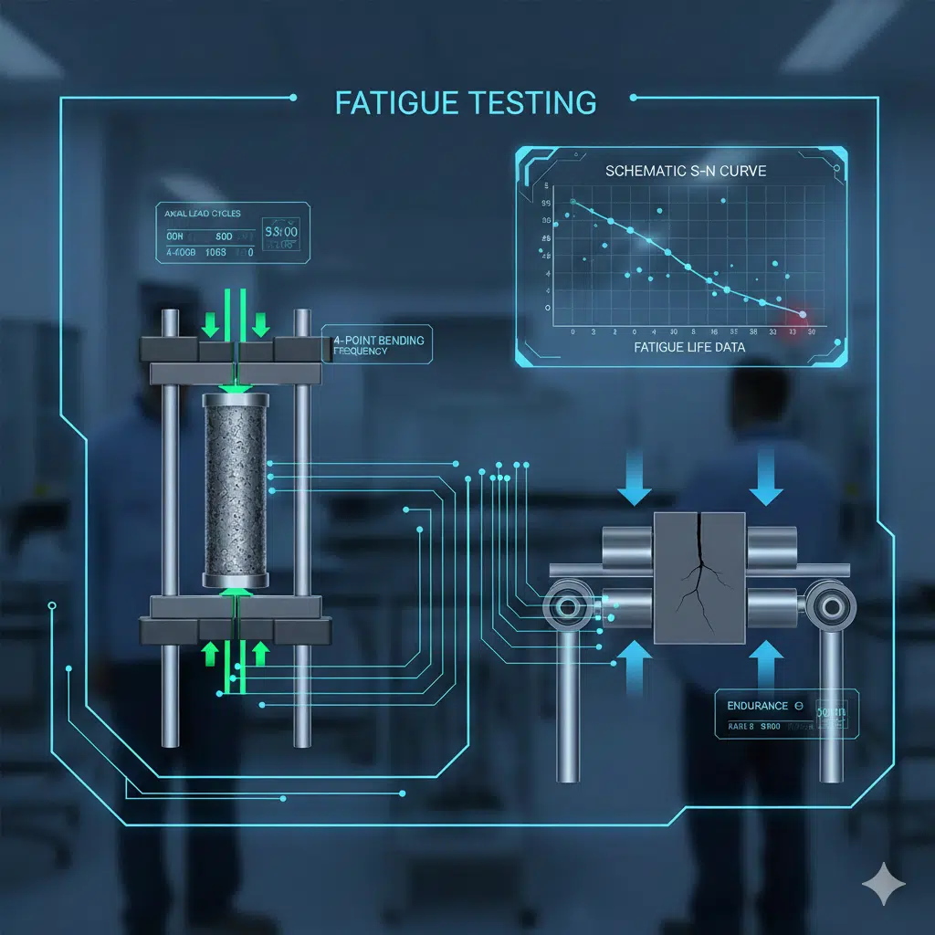
Table of Contents
Introduction
If you’ve ever watched your FEA fatigue predictions diverge significantly from physical test results, you understand the fundamental challenge we face as structural analysts. Fatigue testing bridges this critical validation gap—providing the empirical data that transforms our simulation assumptions into verified design parameters. With 80-90% of mechanical failures originating from cyclic loading conditions, the stakes couldn’t be higher.
The disconnect between predicted and measured fatigue life often stems from factors our models struggle to capture: surface finish variations, residual stresses from manufacturing, and environmental interactions that accelerate crack initiation. Professional testing services don’t just validate our work—they expose the blind spots in our analysis methodology.
This guide covers the fundamentals you need to specify and interpret fatigue testing programs effectively: failure mechanisms, test method selection, standards compliance, composite material considerations, and fracture mechanics integration. Whether you’re validating a new alloy selection or correlating your FEA models, understanding these testing principles is essential for delivering reliable structural designs.
What Is Fatigue Testing and Why It Matters for Structural Integrity
Fatigue testing is a destructive mechanical test method that subjects specimens to repeated cyclic loading to determine the number of cycles a material or component can withstand before crack initiation and eventual fracture occurs. This data forms the foundation for S-N curves, strain-life relationships, and damage tolerance assessments that drive our design decisions.
Fatigue testing is a specialized form of mechanical testing that determines a material’s ability to endure cyclic fatigue loading conditions. The method helps experts predict the material’s lifespan in specific conditions and evaluate the material’s crack resistance and fatigue strength. For FEA professionals, test data serves a dual purpose: validating our analytical predictions and providing material constants we can’t obtain any other way.
This test method is widely used in the aerospace, automotive, and structural engineering industries to evaluate the fatigue life of metals in components like aircraft structures, engine parts, bridges, and pressure vessels. The data generated from testing helps in material selection, failure analysis, and fatigue-resistant design improvements.
Fatigue Failure Mechanisms in Engineering Materials
The stress intensity factor K quantifies the stress field surrounding a crack tip, serving as a single-parameter descriptor of crack-driving force. Paris’ law reveals that crack growth rate follows a power-law relationship with the stress intensity range—small changes in applied stress or crack length can produce significant variations in propagation rate due to the exponential term m (typically ranging from 2 to 4 for most engineering materials).
The constants C and m must be obtained empirically through controlled fatigue testing programs where specimens with pre-existing cracks are cycled under known loading conditions. By measuring crack length as a function of cycle count and calculating corresponding ΔK values, engineers can determine these material parameters for specific alloy systems and environmental conditions, enabling predictive life calculations for service components.
💡 Pro Tip: When correlating FEA results with test data, remember that Paris law constants vary significantly with environment, temperature, and stress ratio. Always verify your material database values match your actual service conditions.
Understanding fatigue failure requires recognizing its three sequential stages: crack initiation at stress concentrations, stable crack growth controlled by fracture mechanics principles, and final unstable fracture when the remaining cross-section can no longer withstand the applied loads. Accurate FEA models must account for each of these phases to predict component life reliably.
The stable crack propagation stage is governed by Paris’ law (also called the Paris-Erdogan equation), which establishes the relationship between crack growth rate and applied stress conditions. This fundamental equation takes the form:
$$\frac{da}{dN} = C(\Delta K)^m\tag{1}$$
Where:
- $\frac{da}{dN}$ represents the crack growth rate per loading cycle
- $\Delta K$ is the stress intensity factor range (the difference between maximum and minimum stress intensity during a cycle)
- $C$ and $m$ are material-specific constants determined through fatigue testing

Correlation Between FEA Predictions and Physical Test Results
The gap between simulation and reality typically manifests in three ways: overpredicted fatigue life (our models miss stress concentrations), underpredicted life (we’re too conservative with safety factors), or inconsistent scatter (we haven’t captured the statistical nature of fatigue).
Common sources of discrepancy include mesh-dependent stress results at notches, idealized boundary conditions that don’t reflect actual constraint, and material properties from handbooks that don’t match your specific heat treatment. Professional fatigue testing programs help quantify these uncertainties and calibrate your analysis approach.
Fatigue Test Methods: Selecting the Right Protocol for Your Application
Fatigue testing is performed using servo-hydraulic equipment operating in load, strain, or position control modes, with temperature capabilities spanning from liquid helium temperatures to over 2000°F. Selecting the right test configuration demands careful alignment between laboratory protocols and real-world service conditions—components subjected to multiaxial loading in operation cannot be fully characterized through uniaxial coupon testing alone. Understanding these limitations is essential when extrapolating test data to complex stress states.
Axial, Bending, and Torsional Loading Configurations
The stress ratio, or R-ratio (minimum stress divided by maximum stress), establishes the loading regime for any fatigue test:
– R = -1: Fully reversed loading (tension-compression)
– R = 0: Zero-to-tension (pulsating tension)
– R = 0.1: Tension-tension with small mean stress
– R > 0.5: High mean stress conditions

Axial fatigue testing delivers the broadest applicability among standard configurations. By applying uniform stress throughout the specimen’s cross-section, this approach accommodates any stress ratio—from fully reversed loading (R = −1) to zero-to-tension cycles (R = 0). These characteristics make axial testing the preferred method for developing S-N curves and establishing endurance limits.
Four-point bending provides an alternative approach where load is distributed through four contact points, generating a constant bending moment between the inner supports while eliminating shear stress from the test section. This setup excels for brittle materials, coating systems, and applications where surface crack initiation drives failure, making it particularly valuable for validating flexural-dominated finite element models.
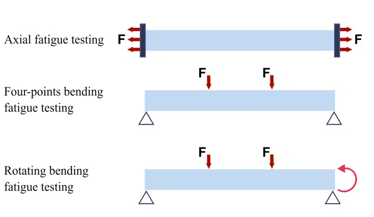
Rotating bending fatigue testing offers an economical solution for high-cycle screening applications, with equipment costs typically 20–25% of servo-hydraulic axial systems and operating frequencies reaching 100 Hz. As the specimen rotates, each surface location cycles between tension and compression, automatically producing fully reversed loading at R = −1. The stress distribution—peaking at the surface and reaching zero at the center—makes this method especially suited for detecting surface-initiated cracks, though it may overlook subsurface defects that axial fatigue testing would reveal.
Crack growth curves are shown for values of stress ratio R ranging from -1 (fully reversing load) to +0.7. Increasing R shifts the crack growth rate up without affecting the slope of the growth rate curve.
⚠️ Common Mistake: Specifying R = 0.1 testing when your component actually experiences R = -1 service loading. The mean stress effect can shift fatigue life by an order of magnitude—always match your test R-ratio to service conditions.
Strain-Controlled vs. Load-Controlled Testing Approaches
The low cycle fatigue (LCF) test to ISO 12106 and ASTM E606 is a fatigue test in which a cyclic load is simulated until failure. The choice between strain control and load control depends on your fatigue regime:
High-cycle fatigue (HCF) achieves a large number of cycles with stress levels typically below the yield strength of the material. These tests are typically force-controlled and can run through one million cycles or more.
The low cycle fatigue test runs in strain control with the load being a dependent variable. When plastic deformation occurs each cycle—typical of thermal cycling or high-stress applications—strain control captures the actual material response.

ASTM and Industry Standards for Fatigue Life Characterization
ASTM E647-24 provides the Standard Test Method for Measurement of Fatigue Crack Growth Rates, while E606/E606M-21 covers Strain-Controlled Fatigue Testing, and E466-21 addresses Conducting Force Controlled Constant Amplitude Axial Fatigue Tests of Metallic Materials.
Specifying the correct standard early in your program prevents costly re-testing and ensures your data will be accepted by certification authorities. Each standard defines specimen geometry, loading parameters, data acquisition requirements, and reporting formats.
Key ASTM Standards for Metallic and Composite Materials
ASTM E606 covers strain-controlled fatigue testing for cases where plastic deformation occurs, complementing the force-controlled approach of E466. For fracture mechanics applications, ASTM E647 describes the determination of fatigue crack growth rates.
Results can support such activities as materials research and development, mechanical design, process and quality control, product performance, and failure analysis.
📋 Quick Reference: For most metallic component validation, start with E466 for S-N data. Add E606 if you’re in the LCF regime (<10⁵ cycles), and E647 if you need crack growth rates for damage tolerance analysis.
Composite and Advanced Materials: Special Fatigue Testing Considerations
Composite fatigue testing requires specialized protocols because damage accumulates through multiple mechanisms—matrix cracking, delamination, and fiber breakage—rather than the single crack propagation mode typical of metallic materials. This fundamentally changes how we interpret test results and validate our FEA models.
This test method can be utilized in the study of fatigue damage in a polymer matrix composite such as the occurrence of microscopic cracks, fiber fractures, or delaminations. The specimen’s residual strength or stiffness, or both, may change due to these damage mechanisms.
Damage Accumulation Monitoring in Laminated Structures
For composites, fatigue is essentially created by initiation, growth, and propagation of a multitude of cracks. The evolution of damage is influenced not only by the materials of matrix and fibers but also by the composition of the laminate.
Unlike metals where we track a single dominant crack, composite fatigue testing monitoring requires:
– Stiffness degradation tracking: Periodic modulus measurements reveal distributed damage
– Acoustic emission monitoring: Real-time detection of matrix cracking and delamination events
– Thermal imaging: Identifies damage zones through heat generation during cycling
The loss in stiffness may be quantified by discontinuing cyclic loading at selected cycle intervals to obtain the quasi-static axial stress-strain curve. The loss in strength associated with fatigue damage may be determined by discontinuing cyclic loading to obtain the static strength.
Fracture Toughness Integration: Connecting Fatigue and Damage Tolerance
Fracture toughness testing determines a material’s resistance to crack propagation, providing critical input data for damage tolerance analysis. Combined with fatigue crack growth rates from E647 testing, engineers can predict inspection intervals and remaining component life with confidence.
Fatigue crack growth testing characterizes the rate at which a preexisting crack will grow under varying stress states. The test measures a crack’s growth rate from a preexisting sharp “starter crack” under the controlled application of a cyclic load.
The integration of S-N data, crack growth rates, and fracture toughness creates a complete picture: initiation life from S-N curves, propagation life from Paris law integration, and critical crack size from K_IC. This damage tolerance approach is mandatory for aerospace structures and increasingly adopted in other safety-critical industries.
How Long Does Professional Fatigue Testing Take? Timeline and Planning Factors
Fatigue testing duration ranges from hours for low-cycle tests to several weeks for high-cycle fatigue characterization. Test frequency, target cycle count, specimen quantity, and required statistical confidence directly impact total program timeline.
Testing per ASTM standards, low-cycle fatigue testing is targeted to run no more than 100,000 cycles. Depending on the material and customer requirements, test frequency can range from 0.25 Hz to more than 5 Hz.
Test frequencies can range between 20 Hz and 60 Hz, depending on the material and required environmental conditions. At 20 Hz, reaching 10⁷ cycles requires approximately 139 hours—nearly six days of continuous testing per specimen. Multi-specimen programs for statistical characterization can extend to several months.
Conclusion
Professional fatigue testing provides the empirical foundation that transforms FEA predictions into validated designs. We’ve covered the essential elements: understanding failure mechanisms from crack nucleation through Paris law propagation, selecting appropriate test methods that match your service conditions, navigating ASTM standards for consistent and certifiable data, and addressing the unique challenges of composite materials testing.
The key insight for FEA professionals is that testing and simulation are complementary—not competing—approaches. Your analysis identifies critical locations and predicts trends; testing validates those predictions and provides the material constants your models require.
Your next step: Review your current FEA fatigue predictions against available test data. Identify where validation gaps exist—whether in material properties, loading assumptions, or environmental factors—and scope a targeted testing program with an accredited laboratory.
Finally, if you liked to know more about S-N curve for fatigue testing, please read:
Understanding S-N Curve: The Foundation of Fatigue Analysis blog
Frequently Asked Questions (FAQ)
What is the fatigue test?
A fatigue test is a destructive mechanical testing procedure that applies repeated cyclic loading to a specimen until failure occurs. This establishes fatigue life data essential for component design validation and FEA model correlation. The method measures how many cycles the material can withstand before fracture.
How to perform fatigue testing?
Fatigue testing requires mounting a prepared specimen on servohydraulic equipment, programming cyclic load parameters (amplitude, frequency, R-ratio), and running until specimen fracture. A suitable extensometer is required for strain control. Data acquisition captures cycle count, load, and displacement throughout testing.
Is fatigue testing destructive?
Yes, fatigue testing is inherently destructive—specimens are loaded cyclically until crack initiation and complete fracture occur. This destructive nature necessitates statistical sampling approaches and careful specimen selection to characterize material performance accurately for design validation purposes.
Why is fatigue testing important?
Fatigue testing helps prevent unexpected failures in critical components, especially in aerospace, automotive, and structural applications. Since fatigue causes 80-90% of mechanical failures, testing provides critical data for design verification, FEA model validation, and regulatory compliance in safety-critical applications.
How long does fatigue testing take?
Fatigue test duration depends on the material, applied stress, and required number of cycles. Low-cycle fatigue tests may complete in hours, while high-cycle tests targeting 10 million cycles at 20 Hz require approximately one week. Multi-specimen statistical programs extend timelines proportionally.

I am a mechanical engineer in the fields of thermal energy storage, fluid mechanics and heat transfer. I have obtained my PhD from KTH Royal Institute of Technology in designing robust and compact additively manufactured prototypes. During my PhD, I worked on CFD modeling and optimization of innovative heat exchanger designs and conducted experiments of the manufactured prototypes in laboratory environments.
In June 2019, I managed to secure the funding for continuation of my PhD by receiving a grant of 3.7 MSEK from the Swedish Energy Agency on development of 3Dprineted air-PCM heat exchangers.