
Key Takeaways
- Substructuring condenses thousands of interior DOF into a superelement carrying only the retained (master) DOF — with zero approximation in linear statics.
- A substructure is generated once and reused many times — repeated components, design reanalysis, and isolating nonlinearity are where the savings multiply.
- The most common failure point is retained-DOF selection: when in doubt, retain the DOF.
Table of Contents
Introduction
Substructuring is the oldest model-order-reduction trick in finite element analysis — and still one of the most misunderstood. Done right, it turns a component with hundreds of thousands of degrees of freedom into a compact superelement that assembles and solves in seconds, with no loss of accuracy in linear statics. Done wrong, it silently deletes vibration modes, produces spurious frequencies, and locks boundary conditions into places you can never change again. This guide explains how substructuring works, when it pays off, how to choose retained DOF, and why component mode synthesis (Craig–Bampton) should be your default for any dynamic analysis.
What Is Substructuring in FEA?
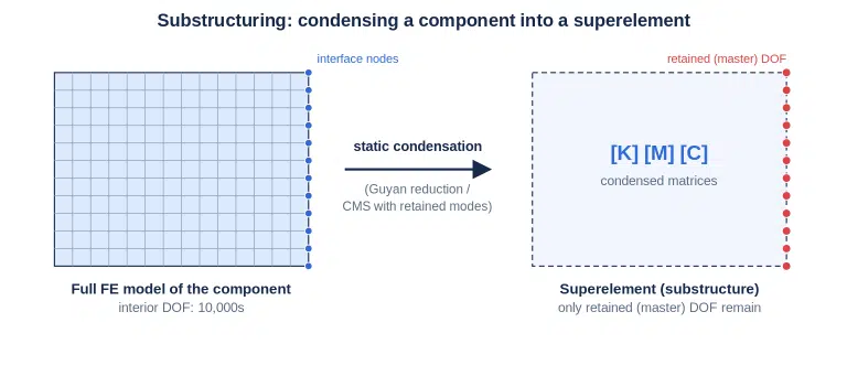
Substructuring is a finite element technique that condenses a group of elements into a single matrix representation — a superelement — by eliminating all degrees of freedom except a user-selected set of retained (master) DOF. The condensed stiffness, mass, and damping matrices reproduce the component’s linear response exactly at the retained DOF.
The reduction is performed once, in its own analysis. The resulting superelement is then used like any other element: connected to the rest of the structure at its retained nodes, instantiated multiple times, translated, rotated, or mirrored. Because the interior DOF are gone from the global equation system, the assembly solves dramatically faster — and any nonlinear iteration in the surrounding structure operates on the reduced DOF set only.
Substructuring vs. Submodeling: Not the Same Thing
Engineers routinely confuse these two techniques, and the difference is fundamental. Substructuring is an exact reduction of a linear region that remains fully coupled to the assembly — forces flow both ways through the retained DOF. Submodeling is a sequence of two separate analyses in which a coarse global solution drives a refined local model one way, with no feedback. Use substructuring when a linear region should participate in the solution; use submodeling when a local detail needs more resolution than the global model can afford.
Where the Savings Come From
A superelement pays for itself through five distinct mechanisms: smaller system matrices in every solve; reuse of one condensation across many instances; cheap reanalysis when design changes occur outside the substructure; isolation of nonlinearity, so Newton iterations touch only the non-reduced elements; and multilevel nesting — substructures inside substructures, as in aircraft models where stringers sit inside flaps inside wings.
📋 Quick info: Substructuring assumes the condensed region behaves linearly (small strains, no contact status change, no plasticity inside). Large rigid-body translations and rotations of the whole superelement are fine in most implementations — mechanisms and vehicle dynamics rely on exactly this.
How Static Condensation Works
Static condensation partitions the component’s equations into retained (r) and eliminated (e) DOF, solves the eliminated set in terms of the retained set, and substitutes back. The condensed stiffness Kₛ = Kᵣᵣ − KᵣₑKₑₑ⁻¹Kₑᵣ is mathematically exact: for linear statics, a substructured model must match the full model to solver precision. Any difference is a modeling error, not an approximation.
Every solver implements the same three-pass workflow, under different names:

Loads acting on the interior of the component deserve special attention. They must be condensed into load vectors during generation and scaled at the use pass — after generation, these pre-packaged load cases are typically the only loading the superelement can carry. Boundary conditions are even stricter: a constraint applied to an eliminated DOF is baked into the matrices permanently and can never be removed later.
💡 Pro Tip: When in doubt, retain the DOF. Retained DOF stay fully available for boundary conditions, constraint equations, couplings, and loads at the use pass. A few extra retained DOF cost almost nothing; a missing one costs a full regeneration.
Guyan Reduction vs. Craig-Bampton (CMS) for Dynamics
For dynamics, the mass matrix must be condensed too — and here the exactness ends. Guyan reduction condenses mass with the same transformation as stiffness, concentrating all inertia at the retained DOF. The eliminated region responds statically, which is accurate only when its inertial effects are genuinely negligible.
The classic benchmark results are sobering. In a simply supported plate study, retaining only the connection DOF shifted the first natural frequency by 4 % — and no amount of additional retained DOF fixed it unless they were the right ones. Retaining in-plane DOF produced spurious hourglass-pattern modes; a retained-node layout that happened to sit on a mode’s nodal lines made that mode vanish entirely from the solution.
Component mode synthesis (CMS) — the Craig-Bampton method in its fixed-interface form — solves this by enriching the reduction basis with the substructure’s own eigenmodes, whose amplitudes become extra generalized DOF at the use pass:

| Aspect | Guyan Reduction | Craig-Bampton CMS |
|---|---|---|
| Statics | Exact | Exact |
| Dynamics | Approximate; degrades with interior inertia | Accurate with modest mode counts |
| Retained-DOF choice | Critical — wrong choice loses or corrupts modes | No longer critical |
| Extra cost | None | One eigenvalue extraction at generation |
| Typical frequency error | 5–300 % on higher modes | < 0.1 % with adequate modes |
Interface variants: fixed-interface (Craig-Bampton) modes are computed with retained DOF constrained; free-interface (Craig-Chang) and mixed-interface modes leave them unconstrained. Free-interface bases often need fewer modes, and the selection rule “include all modes in the frequency range of interest” usually just works — check your loading’s frequency content first.
How to Use Substructuring: 7-Step Workflow
Follow these steps in any FEA package that supports superelements:
- Confirm the region is linear. No plasticity, no contact status changes, no large local strains inside the substructure. Preload effects (e.g., centrifugal stress stiffening) can be built in via a nonlinear preload step before generation.
- Mesh the component and list every DOF you will ever need at the use pass — connection nodes, future boundary conditions, constraint-equation members, output locations. Retain them all.
- Run the generation pass. Request the mass matrix explicitly if any dynamics follows (it is rarely generated by default), select retained eigenmodes for CMS, and package interior loads as load cases.
- Decide on result recovery. Storing the recovery (expansion) data costs disk; skipping it forfeits all interior stresses permanently. Restrict recovery to the element set you actually care about.
- Assemble the use pass. Instantiate, translate, rotate, or mirror the superelement; connect it at retained nodes; reapply any boundary conditions that existed during a preload; scale load cases.
- Verify positioning. Most solvers check retained-node coordinates against the generation geometry within a tolerance — treat any position warning as an error, not noise.
- Expand and post-process. Recover interior displacements and stresses, and combine the per-superelement results with the residual-structure results for plotting.
When to Use Substructuring (and When Not To)
Substructuring pays when a linear region is repeated (generate once, instantiate many times), when it isolates nonlinearity (condense the linear 90 % of a model so iterations touch only the nonlinear 10 %), in cyclic structures with non-cyclic loading, in assembly-level dynamics via CMS, and for exporting flexible bodies to multibody dynamics simulation. It is also a clean way to share components between teams — or with suppliers — without exposing proprietary mesh and material data.
Skip it when the region is nonlinear, when its geometry will change during design iteration (each change forces regeneration), or when the model is small — condensation overhead can exceed the savings. And if both the structure and the loading are cyclically symmetric, plain symmetry boundary conditions are cheaper. For refining a local stress detail such as a weld toe in a welded structure, submodeling is the right tool, not substructuring.
Frequently Asked Questions (FAQ)
What is substructuring in FEA?
Substructuring condenses a group of finite elements into a single superelement by eliminating all DOF except user-selected retained (master) DOF. The condensed matrices reproduce the component’s linear behavior exactly, so large assemblies solve faster while the region remains fully coupled to the rest of the model.
What is a superelement?
A superelement is the practical product of substructuring: a matrix-level element containing the condensed stiffness, mass, damping, and load vectors of a component. It connects to the rest of the model through its retained nodes and behaves like any other element in the assembly.
Does substructuring work for nonlinear analysis?
The substructure itself must remain linear (optionally about a preloaded state), but it can be used inside a nonlinear model — that is one of its biggest payoffs. Nonlinear iterations then operate only on the non-reduced DOF, while most implementations also allow large rigid-body motion of the superelement.
What is the difference between substructuring and submodeling?
Substructuring is an exact, two-way-coupled reduction of a linear region within one solution. Submodeling is two independent analyses: a coarse global model drives a refined local model with no feedback. See our companion guide on submodeling and global-local analysis.
References (clickable):
- Guyan, R.J., “Reduction of Stiffness and Mass Matrices,” AIAA Journal, Vol. 3, No. 2 (1965), p. 380.
- Craig, R.R. and Bampton, M.C.C., “Coupling of Substructures for Dynamic Analyses,” AIAA Journal, Vol. 6, No. 7 (1968), pp. 1313–1319.
- Craig, R.R. and Kurdila, A.J., Fundamentals of Structural Dynamics, 2nd ed., Wiley (2006) — Chapters on component mode synthesis.
- Cook, R.D., Malkus, D.S., Plesha, M.E., and Witt, R.J., Concepts and Applications of Finite Element Analysis, 4th ed., Wiley (2002) — static condensation and substructuring.
- NAFEMS, “Using the Superelement Approach to Improve Automotive FEA,” NWC21-189 (2021).
- Qu, Z.-Q., Model Order Reduction Techniques with Applications in Finite Element Analysis, Springer (2004).

I am a senior CAE and Automation Engineer at Scania with over 9 years of hands-on experience in Finite Element Analysis (FEA). My daily work involves advanced simulations focusing on strength and durability analysis, helping design more reliable and efficient products.
Before joining Scania, I conducted research at KTH Royal Institute of Technology, where I focused on the additive manufacturing of heat exchangers. My work has been recognized internationally and published in peer-reviewed journals. You can find my publications on Google Scholar.
I am a senior CAE and Automation Engineer at Scania with over 9 years of hands-on experience in Finite Element Analysis (FEA). My daily work involves advanced simulations focusing on strength and durability analysis, helping design more reliable and efficient products.
Before joining Scania, I conducted research at KTH Royal Institute of Technology, where I focused on the additive manufacturing of heat exchangers. My work has been recognized internationally and published in peer-reviewed journals. You can find my publications on Google Scholar.