Bolted Joints: Interactive Guide to Preload, Stiffness, Fatigue and Shear

Key Takeaways
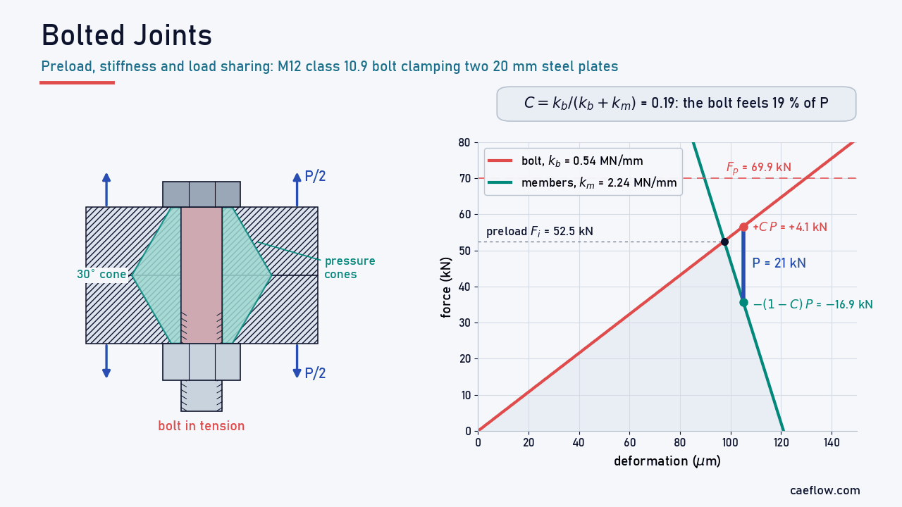
- A preloaded bolted joint is two springs: a stretched bolt and compressed members. The joint stiffness constant \(C = k_b/(k_b + k_m)\) sets how an external load is shared. In the M12 example below, \(C = 0.19\), so the bolt feels only 19 % of the load while the joint stays closed.
- Most tightening torque is lost to friction. With friction coefficients of 0.15, only about 12 % of the torque on an M12 bolt stretches it; 41 % is lost in the thread and 48 % under the nut.
- The nut factor turns torque into preload, \(T = K F_i d\), but friction scatter makes torque a poor measure of preload. Shigley's \(K \approx 0.20\) is a typical value, not a guarantee.
- Preload protects the bolt in fatigue while the joint stays closed. In the example, the Goodman factor of safety is 2.32 with preload and 1.12 if the same bolt carried the full load without preload.
- Shear joints grip by friction or bear on the bolts. Check the slip resistance \(\mu m n F_i\) first. If the joint can slip, check bolt shear, bearing and net-section tension, and add secondary shear for eccentric bolt groups.
Introduction
A bolt that breaks is rarely just too small. Many problems with bolted joints trace back to the clamp force: too little preload, preload lost after assembly, or a joint that opens under load so that the full alternating force reaches the thread.
This guide follows Chapter 8 of Shigley's Mechanical Engineering Design and turns each step into an interactive model: thread geometry, power screws, the torque–preload relation, bolt and member stiffness, the joint diagram, bolt fatigue and shear joints. Every figure, result and safety factor responds to your inputs, so the page also works as a bolted joint calculator for a simple two-plate joint.
What Is a Bolted Joint?
A bolted joint is a connection in which a tightened bolt and nut clamp two or more parts together. Tightening stretches the bolt and compresses the parts by an equal force, the preload. Because the clamped parts are usually much stiffer than the bolt, an external load mostly reduces their compression and adds only a small part to the bolt force.
Bolted joints are loaded in two basic ways. In a tension joint, the load acts along the bolt axis and tries to separate the parts, as in a flange, a cylinder head or a hanging bracket. In a shear joint, the load acts across the bolt axis and tries to slide the parts over each other, as in a lap splice. Many real joints see both.
Set Up the Example Joint
drives every section belowEvery tension and shear model on this page uses one joint: a through-bolt with hex head and regular hex nut, ISO coarse thread, two clamped plates and no washers. The default is an M12 × 1.75 class 10.9 bolt clamping two 20 mm steel plates, which is also the worked example below. Property class 10.9 means a nominal tensile strength of 1000 MPa and a nominal yield-to-tensile ratio of 0.9; the models use the ISO 898-1 minimum values. The power-screw section has its own inputs.
Thread Geometry and Tensile Stress Area
Shigley 8-1A bolt loaded in tension usually fails in its threaded section, not its shank. Tensile tests show that a threaded rod is about as strong as a plain rod whose diameter is the mean of the pitch and minor diameters. The area of that rod is the bolt tensile stress area \(A_t\), used for every axial bolt stress in this guide. For M12 × 1.75, \(A_t\) = 84.3 mm², 25 % less than the 113.1 mm² of the plain shank.
Multiplying \(A_t\) by the proof strength \(S_p\) gives the proof load \(F_p\), the largest force the bolt carries without permanent set: 84.3 mm² × 830 MPa = 69.9 kN for M12 class 10.9. Switch the bolt size and compare \(A_t\) with \(A_d\): the ratio \(A_t/A_d\) rises from 0.71 for M6 to 0.80 for M36, because the pitch grows more slowly than the diameter.
ISO metric threads have a 60° included angle (half-angle α = 30°). The diameters and areas of the basic profile are:
Sp = proof strength (Shigley: for materials without a listed Sp, use Sp ≈ 0.85 Sy). The proof load is the largest load the bolt carries without permanent set.
Power Screws: Torque, Efficiency and Thread Stresses
Shigley 8-2A power screw turns torque into a large axial force, as in screw jacks, vises, presses and lead-screw actuators. It belongs in a guide to bolted joints because tightening a nut is the same problem: the nut climbs a thread ramp against an axial force while its face rubs on the clamped part.
The defaults reproduce Shigley's Example 8-1: a 32 mm double-start square thread with 4 mm pitch lifting 6.4 kN, with friction coefficients f = fc = 0.08 and a 40 mm collar. Raising needs 26.18 N·m, of which the collar takes 10.24 N·m, so the overall efficiency is only 0.311. The thread alone is not self-locking, because \(\pi f d_m\) = 7.54 mm is less than the 8 mm lead, so the lowering thread torque is negative (−0.466 N·m). Only the collar friction holds the load: 9.77 N·m is still needed to lower it.
Step through the screw jack: what F is, what turning the handle does, why one turn of thread is a ramp, and where the torque goes.
1. What is F?
F is the axial force the screw pushes against. In this jack it is the weight sitting on top: F = m·g = 6.40 kN, which is about 652 kg. In a vise or press, F is the clamping force; in a lead-screw actuator it is the thrust. It always acts along the screw axis (dashed line), and it is the same F in every equation on this page.
Several threads share the load. Does that change the torque?
Drag sideways on the 3D view to rotate it. Step through the four stages and switch the load pattern: the torque stays the same, only the peak thread stress changes.
A. The load spreads over the engaged threads
The nut holds the screw up through every engaged thread, all the way around. Each blue arrow is the nut pushing up on one small patch of screw thread. Shigley (Sec. 8-2, from tests): the first thread carries about 38 % of F, the second 25 %, the third 18 %, and the seventh almost none. The 4th to 6th are drawn as 10, 6 and 3 % so the patches add up to F. Where the peak sits depends on how the screw and nut are loaded; thread 1 here is the one next to the loaded face.
Where the thread stresses come from
Shigley's Example 8-1 lists five stresses, each with its own cause. This cut-away isolates the most heavily loaded thread and builds each stress from what physically produces it, ending with the von Mises stress at the thread root. Values follow the inputs below (square-thread geometry, Shigley's Eqs. 8-10 to 8-12).
1. Which thread carries the load?
The nut holds the screw up through its threads. The section shows the square-thread profile: screw threads (grey) rest on nut threads (blue-grey). Only the loaded flank touches; the other flank has clearance. The threads do not share F equally: Shigley (Sec. 8-2) reports from tests that the first engaged thread carries about 38 %, the second 25 %, the third 18 %. So every thread stress below uses 0.38F = 2.43 kN on one thread (nt = 1). That is the most loaded thread, highlighted in orange.
Symbols: F axial load on the screw (here the lifted weight), dm mean thread diameter, l lead (axial advance per turn), f thread friction, fc and dc collar friction and mean collar diameter. Multiplying the ramp force P by dm/2 gives the torque; that is all these equations do.
Defaults are Shigley Example 8-1 (32 mm square thread, p = 4 mm, double-start, F = 6.4 kN, f = fc = 0.08, dc = 40 mm). The page reproduces the book's answers: TR = 15.94 + 10.24 = 26.18 N·m, TL = −0.466 + 10.24 = 9.77 N·m, e = 0.311, τ = 6.07 MPa, σ = −10.39 MPa, σB = −12.9 MPa, σb = 41.5 MPa, σ′ = 48.7 MPa.
Torque and Preload: The Nut Factor K
Shigley 8-8Tightening a nut is a power screw raising the preload \(F_i\), plus a collar: the nut face rubbing on the member. Shigley collects thread geometry, thread friction f and collar friction fc into one torque coefficient, the nut factor K, so that \(T = K F_i d\). With f = fc = 0.15, K ≈ 0.20 for any size; the M12 example gives K = 0.1967.
The torque split shows why preload is so uncertain. Only about 12 % of the torque stretches the bolt; 41 % is lost in the thread and 48 % under the nut, so a small change in friction changes the preload a lot at the same torque. Click the K values from Shigley's Table 8-15 to see it. Shigley recommends a preload of 0.75 Fp for reused fasteners and 0.90 Fp for permanent joints. For the example, 0.75 Fp = 52.5 kN needs 123.8 N·m, rounded to 124 N·m.
A nut on a bolt is a power screw that is "raising" the preload Fi, plus a collar. Apply the Acme-style equation with α = 30° and collect everything into one torque coefficient K.
| Shigley Table 8-15 · bolt condition | K | |
|---|---|---|
| Nonplated, black finish | 0.30 | |
| Zinc-plated ≈ current | 0.20 | |
| Lubricated | 0.18 | |
| Cadmium-plated | 0.16 | |
| With anti-seize compound | 0.12 |
Torque is a poor indicator of preload. In the Blake and Kurtz tests reported in Shigley's Tables 8-13 and 8-14, ½-20 UNF bolts (12.7 mm, close to M12 × 1.25) all torqued to 90 N·m gave a mean preload of about 34 kN (K ≈ 0.21), with a standard deviation of 4.9 kN unlubricated and 2.9 kN lubricated. Shigley's advice: measure the bolt elongation when the preload must be reliable.
Bolt Stiffness and the Pressure Cone
Shigley 8-4, 8-5How a bolted joint shares an external load depends on two stiffnesses. The bolt is two springs in series: the unthreaded shank and the threaded part inside the grip. The members are compressed inside a pressure cone that spreads from under the head and the nut; Shigley models it as two frusta with a 30° half-apex angle that meet at mid-grip.
In the example the grip is l = 40 mm. The bolt must be longer than l plus the nut height (10.8 mm), so the next preferred length is L = 60 mm. With a thread length LT = 2d + 6 = 30 mm, 30 mm of shank and 10 mm of thread sit in the grip, which gives kb = 0.539 MN/mm. The two steel frusta give km = 2.235 MN/mm, about four times the bolt stiffness, so C = 0.194. Wileman's FEA-based fit gives a 6 % stiffer km. Change one plate to aluminium: km drops, C rises and the bolt takes a larger share of every external load.
The bolt in the grip is the unthreaded shank (Ad, length ld) in series with the threaded part (At, length lt). Shigley ignores head and nut deformation, so the real bolt is slightly softer than kb.
Load spreads from the washer face (dw ≈ 1.5d) down a hollow cone. Each material layer inside a cone is its own frustum, and all frusta act in series.
| Frustum | t (mm) | D (mm) | E (GPa) | k (MN/mm) |
|---|---|---|---|---|
| Head-side · plate 1 | 20.00 | 18.00 | 207 | 4.470 |
| Nut-side · plate 2 | 20.00 | 18.00 | 207 | 4.470 |
| Series total k_m | 2.235 |
The Bolted Joint Diagram: How the Load Is Shared
Shigley 8-7, 8-9The joint diagram plots force against deformation for the bolt (rising line, slope kb) and the members (falling line, slope km). At preload both carry Fi. An external load P stretches the bolt and relaxes the members by the same extra deformation, so the bolt gains C·P and the members lose (1 − C)·P of their compression.
For the example, P = 21.0 kN per bolt (0.3 Fp). The bolt force rises by only 4.08 kN to 56.6 kN, while the clamp force falls by 16.9 kN to 35.6 kN. The joint would open at P0 = 65.2 kN, a separation factor of 3.10. The yield factor np = 1.24 looks low, but by design: the preload alone already uses 75 % of the proof load. The load factor nL = 4.27 shows how far P could grow before the bolt reaches its proof load.
After preload, bolt and members carry the same force Fi at different deformations. An external separating load P adds the same deformation Δ = P/(kb + km) to both, so the stiffer members take most of P as a loss of compression.
Fatigue of Preloaded Bolts
Shigley 8-11When P cycles between 0 and P, the bolt force cycles only by C·P while the joint stays closed. In the example the alternating stress is σa = C P/(2At) = 24.2 MPa on top of a preload stress σi = 623 MPa. Shigley's fatigue diagram uses a load line that starts at σi with slope 1, and the endurance strengths of Table 8-17 already include the thread notch and the rolled-thread finish. See our S-N curve guide for the background.
With the Goodman criterion the example bolt has nf = 2.32 (Gerber 3.57, ASME-elliptic 3.49). Without preload the same bolt would carry the full 0 to 21 kN cycle and Goodman would give only 1.12, so the clamped members roughly double the fatigue margin. For a fixed alternating stress, though, the Goodman factor falls as preload rises, and the benefit lasts only while the joint stays closed.
P cycles between 0 and P. As long as the joint stays closed, the bolt sees only C·P of that range, so a low C and enough preload to prevent separation protect the bolt. The load line starts at σi and has slope 1, because σm = σa + σi.
| Shigley Table 8-17 (rolled threads, fully corrected) | Se (MPa) |
|---|---|
| ISO 8.8 (listed M16–M36) | 129 |
| ISO 9.8 | 140 |
| ISO 10.9 | 162 |
| ISO 12.9 | 190 |
Se rises much less than the static strength from class 8.8 to 12.9 (129 → 190 MPa, while Sut rises 830 → 1220 MPa). A stronger bolt mainly allows a higher preload and mean stress, not a much higher alternating stress. For 8.8 below M16 this page uses 129 MPa as an approximation.
Bolted Joints in Shear
Shigley 8-12A shear joint carries load by friction or by bearing. If the clamp force is high enough, friction at the faying surfaces carries the load and the bolts see no shear. If the joint slips, the bolts bear against the hole walls, and you must check bolt shear, bearing on the bolts and plates, and net-section tension, as in Shigley's Example 8-6.
The defaults load two M12 class 10.9 bolts with 60 kN through a 10 mm × 100 mm plate with Sy = 370 MPa. With μ = 0.2, the slip resistance is only 21.0 kN; holding 60 kN by friction would need 150 kN of preload per bolt, more than twice the proof load. In bearing, plate bearing governs (n = 1.48), ahead of bolt shear (n = 1.81) and net-section tension (n = 4.69). If the threads lie in the shear plane, the bolt-shear factor drops to 1.22.
For an eccentric bolt group, the moment M = V·e adds secondary shear in proportion to each bolt's distance from the centroid. In the four-bolt default (V = 16 kN at e = 150 mm), the two bolts on the load side carry 13.0 kN each, more than three times the 4.0 kN primary shear.
| Mode | Stress (MPa) | Strength | n |
|---|---|---|---|
| Bolt shear | 265.3 | 479 0.577 Sp | 1.81 OK |
| Bearing on bolts | 250.0 | 830 Sp | 3.32 OK |
| Bearing on members governs | 250.0 | 370 Sy plate | 1.48 low |
| Member tension (net section) | 78.9 | 370 Sy plate | 4.69 OK |
| Edge tearing / shear-out | keep edge distance ≥ 1.5d = 18 mm | ||
Eccentric bolt group
Arrows are the forces acting on the bolts, as in Shigley Fig. 8-27. Primary shear F′ = V/n acts on every bolt. The moment M = V·e adds secondary shear proportional to the distance from the centroid, perpendicular to the radius. The worst bolt gets the largest vector sum.
Worked Example: M12 Class 10.9 Tension Joint
The defaults above form a complete bolted joint check for a tension joint. Here it is step by step, so you can reproduce every number by hand.
Worked example
M12 Class 10.9 Bolt Clamping Two 20 mm Steel Plates
Inputs: M12 × 1.75 coarse thread, class 10.9 (Sp = 830 MPa, Sut = 1040 MPa, Se = 162 MPa), two 20 mm steel plates (E = 207 GPa), f = fc = 0.15, washer face 1.5d, hole = d, external load P cycling from 0 to 21.0 kN.
Step 1 · Thread and proof load
Tensile stress area and proof load
Step 2 · Tightening torque
Nut factor and torque for 0.75 Fp
With dm = (12 + 9.853)/2 = 10.93 mm and tan λ = 1.75/(π · 10.93) = 0.0510, Shigley's equation gives K = 0.1967. The target preload is 0.75 Fp = 52.5 kN.
Rounded to 124 N·m, the preload is Fi = 124,000/(0.1967 × 12) = 52.5 kN.
Step 3 · Stiffness
Bolt, members and joint constant
Grip l = 40 mm, nut height 10.8 mm, so L = 60 mm with LT = 30 mm, ld = 30 mm and lt = 10 mm. Each member frustum has t = 20 mm and D = 18 mm.
Step 4 · External load
Bolt force, clamp force and static factors
Separation factor n0 = 3.10, yield factor np = 1.24, load factor nL = 4.27.
Step 5 · Fatigue
Goodman factor of safety
σi = 52,530/84.27 = 623.3 MPa and σa = 0.1943 × 21,000/(2 × 84.27) = 24.2 MPa.
Result: the joint stays closed with a separation factor of 3.10, and the bolt has a Goodman fatigue factor of 2.32. Every intermediate value matches the readouts of the interactive models at their default settings.
Limits of the Shigley Method
Shigley's model is the right starting point for bolted joint design, but it simplifies several effects:
- Preload scatter. Torque control sets preload only as well as friction is known. Use the minimum preload for slip and separation checks and the maximum for bolt-strength checks.
- Preload loss. Embedding of surface roughness, gasket creep and thermal effects reduce preload after tightening. Shigley's model does not include them; VDI 2230 does.
- Head and nut compliance. kb ignores the deformation of the head, the nut and the engaged thread, so the real bolt is softer and C somewhat higher.
- Pressure cone. The 30° cone assumes members wide enough to contain it. Edge bolts, narrow flanges and neighbouring bolts change the stiffness.
- Concentric load. Eccentric loading and prying open the joint on one side and bend the bolt. For complex joints, use VDI 2230 or a finite element analysis with contact and bolt pretension.
Conclusion
Bolted joint design rests on a few linked ideas. The tensile stress area and proof load set the bolt's capacity. The nut factor turns torque into a preload with real scatter. The stiffness ratio C decides how much external load reaches the bolt, and preload keeps the joint closed, which protects the bolt in fatigue and lets friction carry shear. Use the interactive models to build intuition, then check real designs with minimum and maximum preload, a recognised method such as VDI 2230, and FEA where the joint is more than two plates and a bolt.
FAQ
What is the difference between a tension joint and a shear joint?
In a tension joint, the external load acts along the bolt axis and tries to separate the clamped parts; the bolt carries the preload plus a share C·P of the load. In a shear joint, the load acts across the bolt axis and tries to slide the parts. Friction carries it while the clamp force is high enough; otherwise the bolts carry it in shear and bearing.
What is the nut factor K?
The nut factor K is the coefficient in T = K·Fi·d that links tightening torque T, preload Fi and nominal diameter d. It lumps thread geometry, thread friction and nut-face friction. Shigley lists K = 0.30 for non-plated black-finish bolts, 0.20 for zinc-plated, 0.18 for lubricated, 0.16 for cadmium-plated and 0.12 with anti-seize compound.
Why does a preloaded bolt see only part of the external load?
Preload stretches the bolt and compresses the clamped parts. An external tensile load P stretches the bolt further and relaxes the parts by the same amount, so the load splits by stiffness: the bolt gains C·P and the parts lose (1 − C)·P of their compression, where C = kb/(kb + km). Once the joint separates, the bolt carries all of P.
What is the tensile stress area of a bolt?
The tensile stress area At is the effective area used for axial stress in a threaded bolt. For ISO metric threads, At = (π/4)(d − 0.9382p)², the area of a circle whose diameter is the mean of the pitch and minor diameters. For an M12 × 1.75 bolt, At = 84.3 mm².
When is a power screw self-locking?
A square-thread power screw is self-locking when π·f·dm > l, which is the same as f > tan λ, where f is the thread friction, dm the mean diameter, l the lead and λ the lead angle. For an Acme thread, f is replaced by f·sec α. A self-locking screw holds its load without a brake; multi-start screws with a large lead often are not self-locking.
References (clickable):
- Budynas, R. G. and Nisbett, J. K. Shigley's Mechanical Engineering Design, 9th ed. McGraw-Hill, 2011. Chapter 8: Screws, Fasteners, and the Design of Nonpermanent Joints.
Hamid Rastan
I am a senior CAE and Automation Engineer at Scania with over 8 years of hands-on experience in Finite Element Analysis (FEA). My daily work involves advanced simulations focusing on strength and durability analysis, helping design more reliable and efficient products. Before joining Scania, I conducted research at KTH Royal Institute of Technology, where I focused on the additive manufacturing of heat exchangers. My work has been recognized internationally and published in peer-reviewed journals. You can find my publications on Google Scholar.
Equations follow Shigley's Mechanical Engineering Design, 9th ed., Chapter 8. Strengths are ISO 898-1 minimums; for 8.8 up to M16 the ISO values 580/640/800 MPa are used, because Shigley Table 8-11 lists 8.8 only for M16–M36. Steel bolt E = 207 GPa. Hole diameter is taken as d and washer-face diameter as 1.5d. The power-screw Acme equation uses Shigley's sec α approximation. Thread stresses are Shigley's nominal values; real root fillets add stress concentration. Verified against Shigley Ex. 8-1, the Table 8-1 stress areas and Eq. 8-22.
