Reynolds Number: Formula, Critical Values and Calculator
Key Takeaways
- The Reynolds number, $Re = \rho V L/\mu = VL/\nu$, compares inertial and viscous effects in a flow. It is dimensionless, so it has the same value in any consistent set of units.
- Its value depends on the characteristic length: the distance from the leading edge for a flat plate, the diameter for pipes, cylinders and spheres, and the hydraulic diameter $D_h = 4A/P$ for noncircular ducts.
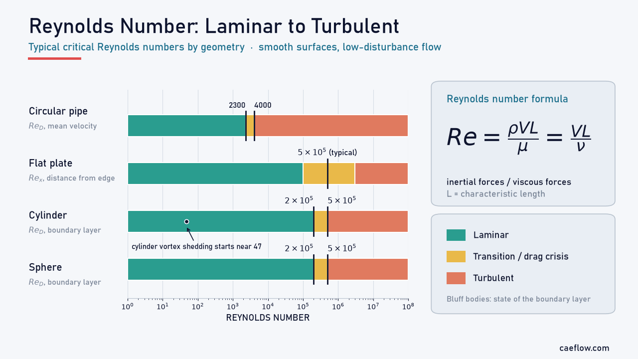
- The critical Reynolds number depends on geometry: about 2300 in a pipe, about $5\times10^5$ on a flat plate, and roughly $2\times10^5$ to $5\times10^5$ for the drag crisis on smooth cylinders and spheres.
- Critical values are engineering guides, not constants: roughness, disturbances and pressure gradients all move transition.
Introduction
Why does syrup pour in a smooth, glassy sheet while a river is full of swirling eddies? Both behaviors are predicted by one dimensionless group, the Reynolds number. It tells an engineer whether a flow is laminar or turbulent, which friction or drag correlation applies, how fine a CFD mesh must be near a wall, and whether a scale model can stand in for the real object.
This guide explains the concept and formula, how to choose the characteristic length (including the hydraulic diameter of noncircular ducts), and the critical values for flat plates, pipes, cylinders and spheres. It ends with a worked example and a free calculator.
What Is the Reynolds Number?
The Reynolds number is a dimensionless number that expresses how strong inertial forces are compared with viscous forces in a moving fluid. At low values viscosity dominates and the flow stays orderly (laminar); at high values inertia dominates and small disturbances can grow into turbulence.
Reynolds Number Formula
The Reynolds number formula combines four quantities:
$$Re = \frac{\rho V L}{\mu} = \frac{V L}{\nu}$$
- $\rho$: fluid density, kg/m³
- $V$: characteristic velocity, m/s (the mean velocity $Q/A$ in a duct, the free-stream velocity around a body)
- $L$: characteristic length, m (see below)
- $\mu$: dynamic viscosity, Pa·s; $\nu = \mu/\rho$ is the kinematic viscosity, m²/s
All units cancel, so the result is identical in SI or US units if the inputs are consistent. The group honors Osborne Reynolds, who in 1883 injected dye into water flowing through glass tubes and showed that the switch from “direct” to “sinuous” motion depends on this combination, not on velocity, diameter or viscosity alone.
Inertial Versus Viscous Forces
A scaling argument shows where the ratio comes from. For a fluid parcel of size $L$ moving at speed $V$, the inertial force (mass times acceleration) scales as $\rho L^3 \cdot V^2/L$, and the viscous force (shear stress times area) as $\mu (V/L) \cdot L^2$:
$$\frac{\text{inertial force}}{\text{viscous force}} \sim \frac{\rho V^2 L^2}{\mu V L} = \frac{\rho V L}{\mu} = Re$$
This is an order-of-magnitude ratio, not a force balance at a point. Equivalently, $Re$ compares the time viscosity needs to diffuse momentum across $L$, namely $L^2/\nu$, with the time the flow needs to carry it past, $L/V$. At high $Re$, disturbances are swept along before viscosity can damp them.
Why the Reynolds Number Matters: Dimensional Analysis and Similarity
Suppose the force $F$ on a body depends only on its size $L$, the stream velocity $V$, and the fluid properties $\rho$ and $\mu$. Dimensional analysis reduces these five variables to two dimensionless groups:
$$\frac{F}{\rho V^2 L^2} = g\left(\frac{\rho V L}{\mu}\right) \quad \text{or} \quad C_F = g(Re)$$
That has two practical benefits:
- One curve instead of thousands of tests. To map $g$ you only need to vary $Re$, for example by changing the tunnel speed, instead of testing many fluids and body sizes.
- Scale-model testing. A geometrically similar model run at the prototype’s Reynolds number has the same force coefficient, as long as no other group matters, which gives the scaling law:
$$\text{If } Re_m = Re_p: \quad \frac{F_p}{F_m} = \frac{\rho_p}{\rho_m}\left(\frac{V_p}{V_m}\right)^2\left(\frac{L_p}{L_m}\right)^2$$
Here $m$ is the model and $p$ the prototype. Matching $Re$ can clash with other groups: a 1:10 model in the same air must run ten times faster, so a 30 m/s prototype needs 300 m/s, about Mach 0.87, where compressibility changes the flow. Water tunnels and pressurized or cryogenic wind tunnels avoid that penalty.
In CFD, the Reynolds number guides the choice between a laminar and a turbulence model, and the first cell height for a target $y^+$ shrinks as $Re$ grows (see our y+ calculator).
Characteristic Length and Hydraulic Diameter
A Reynolds number means little without the length it is based on. The same flow can give values that differ by a factor of two or more, and a critical value applies only to the definition used to measure it.
Choosing the Characteristic Length
- Flat plate: the distance $x$ from the leading edge gives the local $Re_x = Vx/\nu$; the plate length gives $Re_L$.
- Circular pipe: the inner diameter $D$, with the mean velocity.
- Noncircular duct or annulus: the hydraulic diameter $D_h$.
- Cylinder in cross-flow and sphere: the outer diameter $D$, with the free-stream velocity.
- Airfoil: the chord length $c$.
Open-channel flow often uses the hydraulic radius $R_h = A/P$ instead, which gives a value four times smaller than one based on $D_h$. Always use the definition behind the correlation or threshold you compare with.
Hydraulic Diameter for Noncircular Ducts
For a duct of any cross-section, the hydraulic diameter is four times the flow area over the wetted perimeter:
$$D_h = \frac{4A}{P}$$
The wetted perimeter $P$ includes every wall that exerts shear on the fluid, so in an annulus both the inner and outer walls count. For a full circular pipe $D_h = D$. Common cases:
- Rectangle $a \times b$: $D_h = 2ab/(a+b)$; for a square, $D_h = a$
- Concentric annulus: $D_h = D_o - D_i$
- Wide parallel plates with gap $h$: $D_h = 2h$
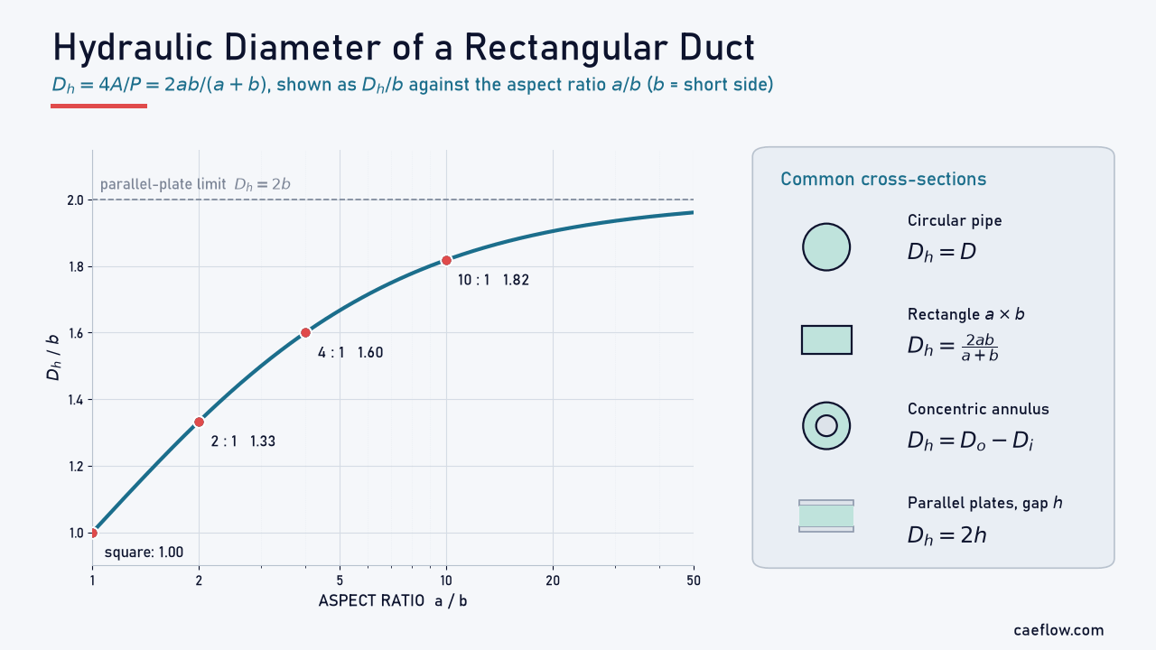
Figure 1. Hydraulic diameter of a rectangular duct divided by its short side, $D_h/b = 2(a/b)/(1+a/b)$. It equals 1 for a square, 1.6 at an aspect ratio of 4, and approaches 2, the parallel-plate limit, for very wide ducts.
In turbulent flow, circular-pipe friction correlations evaluated with $D_h$ are typically within about ±15%. In laminar flow the error can reach about 40%, so use the exact laminar result for the shape, for example $f\,Re_{D_h} = 96$ for parallel plates instead of 64 (White, 2011).
Critical Reynolds Number: Laminar to Turbulent Transition
The critical Reynolds number marks where a laminar flow begins to turn turbulent. Each geometry has its own value, tied to its own characteristic length, and even then it shifts with roughness, inlet or free-stream disturbances, pressure gradient and vibration. Transition also spans a range rather than a single point.
Flat Plate Boundary Layer
On a flat plate at zero pressure gradient, the boundary layer starts laminar at the leading edge and thickens downstream as $Re_x$ grows. The usual engineering value for transition is $Re_{x,cr} \approx 5\times10^5$, typical of commercial surfaces and disturbed streams. A polished plate in a very quiet stream can stay laminar to about $3\times10^6$, while roughness, strong free-stream turbulence or an adverse pressure gradient can trigger transition near $10^5$.
For air at 20 °C and 10 m/s, $Re_x = 5\times10^5$ is reached about 0.75 m from the leading edge; for water at 1 m/s, about 0.50 m. Stability theory uses “critical” for an earlier point: small Tollmien–Schlichting waves start to amplify at $Re_x \approx 9\times10^4$, well upstream of turbulence.
Pipes and Ducts
For fully developed flow in a circular pipe, the accepted design value is $Re_{D,cr} \approx 2300$, based on the mean velocity and inner diameter. Common practice treats:
- $Re_D < 2300$: laminar
- $2300 < Re_D < 4000$: transitional, with intermittent turbulent “puffs”
- $Re_D > 4000$: turbulent
These are design guides. With a smooth, rounded inlet and very quiet inflow, laboratory pipes have stayed laminar far above 2300, while Avila et al. (2011) place the lowest Reynolds number at which turbulence sustains itself near 2040. For parallel-plate channels and annuli, White (2011) gives about 2000 based on $D_h$.
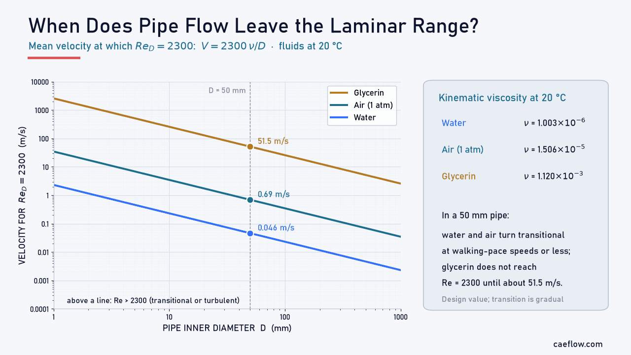
Figure 2. Mean velocity at which $Re_D = 2300$ in a circular pipe, $V = 2300\,\nu/D$, at 20 °C. In a 50 mm pipe, water reaches it at 0.046 m/s and air at 0.69 m/s, while glycerin does not reach it until about 51.5 m/s.
Figure 2 shows why most water and air piping is turbulent, while oils and other viscous liquids often flow laminar.
Cylinders and Spheres
For bluff bodies the Reynolds number uses the diameter, $Re_D = VD/\nu$, and the critical value marks transition in the boundary layer on the body. Below it, the laminar boundary layer separates early, around 80° from the front stagnation point, leaving a wide wake. Above it, the turbulent boundary layer stays attached to about 120°, the wake narrows, and drag falls sharply, from $C_D \approx 1.2$ to about 0.3 for a cylinder (White, 2011).
This drag crisis occurs at roughly $Re_D \approx 2\times10^5$ to $5\times10^5$ for smooth cylinders and spheres. Roughness lowers it, which is why golf balls are dimpled. At much lower values the wake changes too: behind a cylinder, periodic vortex shedding begins near $Re_D \approx 47$.
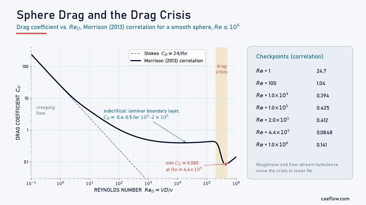
Figure 3. Sphere drag coefficient from the Morrison (2013) correlation, recommended up to $Re = 10^6$. $C_D$ follows $24/Re$ in creeping flow, stays near 0.4 to 0.5 between $10^3$ and $2\times10^5$, then falls to about 0.085 near $4.4\times10^5$ in the drag crisis.
Critical Reynolds Number Table
Table 1 summarizes typical values. Treat them as starting points and check transition for your own conditions.
How to Calculate the Reynolds Number
To calculate the Reynolds number for any flow:
- Decide whether the flow is internal or external and pick the characteristic length used by your correlation.
- Get $\rho$ and $\mu$, or $\nu$, at the fluid temperature; liquid viscosity changes strongly with temperature.
- Use the mean velocity $Q/A$ in a duct, or the free-stream velocity around a body.
- Compute $Re = \rho VL/\mu$ in consistent units and compare it with the critical value for that geometry.
Internal flow · Worked example
Reynolds number of air in a rectangular duct
Air at 20 °C and 1 atm flows at a mean velocity of 4 m/s through a 300 mm × 150 mm duct.
Step 1 · Fluid properties
Look up air properties at 20 °C
$\rho = 1.204$ kg/m³ and $\mu = 1.813\times10^{-5}$ Pa·s, so $\nu = \mu/\rho = 1.506\times10^{-5}$ m²/s.
Step 2 · Characteristic length
Compute the hydraulic diameter
$$\begin{aligned} D_h &= \frac{4A}{P} = \frac{4\,(0.30)(0.15)}{2\,(0.30 + 0.15)} \\ &= 0.20\ \text{m} \end{aligned}$$
Step 3 · Reynolds number
Compute Re and the regime
$$\begin{aligned} Re_{D_h} &= \frac{V D_h}{\nu} = \frac{4 \times 0.20}{1.506\times10^{-5}} \\ &\approx 5.31\times10^4 \end{aligned}$$
Result: $Re_{D_h} \approx 53{,}100$, far above 4000, so the duct flow is turbulent.
Step 4 · Sensitivity
What if the wrong length is used?
Basing Re on the short side (0.15 m) would give about 39,800, 25% low; the long side would give about 79,700, 50% high. Staying below the approximate laminar limit, $Re_{D_h} \approx 2000$, would need a mean velocity under 0.15 m/s, which is why HVAC duct flow is almost always turbulent.
Reynolds Number Calculator
Use this calculator to find the Reynolds number for pipes, rectangular ducts, annuli, flat plates, cylinders and spheres. It also returns the hydraulic diameter, the kinematic viscosity and the expected regime based on Table 1.
The regime is an estimate for smooth surfaces and low-disturbance flow; check the property values at your operating temperature.
Strengths and Limitations of the Reynolds Number Criterion
Strengths:
- One number classifies the regime and selects the right friction, drag or heat-transfer correlation
- Lets scale models and dimensionless data represent full-size equipment
- Quick to compute from standard property data
Limitations:
- Transition also depends on roughness, disturbances, pressure gradient and vibration, so critical values are ranges
- The value depends on the chosen characteristic length and velocity
- Other groups can matter as much: Mach number in compressible flow, Froude number with a free surface, relative roughness in turbulent friction
- Non-Newtonian fluids need a generalized Reynolds number because their viscosity varies with shear rate
- With heating or cooling, properties must be taken at a representative temperature, such as the film temperature
Conclusion
The Reynolds number is the first thing to compute in almost any fluid problem. It condenses velocity, size and fluid properties into one ratio of inertial to viscous effects, decides whether laminar or turbulent physics applies, and lets model tests transfer to full scale.
Its value is only as good as the characteristic length behind it, and the critical values move with roughness and disturbances. Use the calculator for quick checks, then confirm the regime for your own conditions.
FAQ: Common Questions About the Reynolds Number
What is the Reynolds number in simple terms?
It is a dimensionless number that compares the inertial forces in a moving fluid with its viscous forces, $Re = \rho VL/\mu$. A low value means viscosity keeps the flow smooth and layered (laminar); a high value means inertia dominates and the flow tends to become turbulent.
What Reynolds number is turbulent?
It depends on the geometry. In a circular pipe, flow is usually laminar below about 2300, transitional between 2300 and 4000, and turbulent above about 4000. A flat-plate boundary layer typically becomes turbulent near $Re_x = 5\times10^5$, and the boundary layer on a smooth cylinder or sphere near $2\times10^5$ to $5\times10^5$.
How do you calculate the Reynolds number?
Multiply density, velocity and characteristic length, then divide by dynamic viscosity: $Re = \rho VL/\mu$, or $Re = VL/\nu$ with the kinematic viscosity. For example, water at 20 °C flowing at 1 m/s in a 25 mm pipe gives $Re = 1 \times 0.025 / (1.003\times10^{-6}) \approx 24{,}900$, which is turbulent.
What is the critical Reynolds number for a flat plate?
The common engineering value is $Re_x \approx 5\times10^5$, based on the distance $x$ from the leading edge. Over a polished plate in a very quiet stream it can reach about $3\times10^6$, while roughness, free-stream turbulence or an adverse pressure gradient can lower it toward $10^5$.
Which characteristic length should I use in the Reynolds number?
Use the length that matches the correlation or critical value you compare with: the inner diameter for pipes, the hydraulic diameter $4A/P$ for noncircular ducts, the distance from the leading edge for flat plates, the diameter for cylinders and spheres, and the chord for airfoils.
References (clickable):
- White, F. M. (2011). Fluid Mechanics (7th ed.). McGraw-Hill. Chapters 5–7.
- Reynolds, O. (1883). An experimental investigation of the circumstances which determine whether the motion of water shall be direct or sinuous, and of the law of resistance in parallel channels. Philosophical Transactions of the Royal Society of London, 174, 935–982.
- Çengel, Y. A., & Cimbala, J. M. (2018). Fluid Mechanics: Fundamentals and Applications (4th ed.). McGraw-Hill.
- Schlichting, H., & Gersten, K. (2017). Boundary-Layer Theory (9th ed.). Springer.
- Avila, K., Moxey, D., de Lozar, A., Avila, M., Barkley, D., & Hof, B. (2011). The onset of turbulence in pipe flow. Science, 333(6039), 192–196.
- Morrison, F. A. (2013). Data correlation for drag coefficient for sphere. Michigan Technological University.
- Provansal, M., Mathis, C., & Boyer, L. (1987). Bénard–von Kármán instability: transient and forced regimes. Journal of Fluid Mechanics, 182, 1–22.