
Moment of Inertia Calculator: Area Moment of Inertia of Beam Sections
Key Takeaways
- The area moment of inertia (second moment of area) describes how a cross-section’s area is spread about an axis. It sets a beam’s bending stiffness $EI$ and, through the section modulus, its bending stress.
- The free calculator below gives $I_x$, $I_y$, $I_{xy}$, principal values, centroid, section moduli and radii of gyration for ten section types, including any polygon.
- For composite shapes, use the parallel axis theorem about the section centroid: $I_x = \sum (I_{c,i} + A_i d_i^2)$.
- Rolled steel tables include root fillets. For an IPE 200 the sharp-corner value is 5.0% below the catalogue value, so use manufacturer data for design.
Table of Contents
- Key Takeaways
- Introduction
- Moment of Inertia Calculator
- What Is the Area Moment of Inertia?
- Moment of Inertia Formulas for Common Sections
- How to Calculate the Moment of Inertia of a Beam
- Worked Example: T-Section
- Checking the Calculator Against a Steel Table
- Why Section Shape Matters
- Common Mistakes
- Limitations of the Calculator
- Conclusion
- FAQ
- References
Introduction
Whether you are sizing a steel beam, checking a machine frame or defining a beam element in FEA, one of the first numbers you need is the cross-section’s moment of inertia. It controls how much the beam deflects and, together with the distance to the outer fibre, how highly it is stressed.
Below you will find a free moment of inertia calculator, the formulas behind it, a worked example and a check against a steel table.
Moment of Inertia Calculator
Choose a cross-section, enter its dimensions and read the area moment of inertia and related section properties. All results refer to axes through the centroid and update as you type.
How to Use the Calculator
- Pick one of ten shapes. For irregular shapes, choose Polygon and list the corner coordinates in order around the outline.
- Set the input and results units separately, for example mm in and cm⁴ out to compare with European section tables.
- x is horizontal and y is vertical. $I_x$ governs bending in the vertical plane, such as a floor beam loaded from above.
- For angles and other unsymmetric sections, also read $I_1$, $I_2$ and $\theta_p$. They transform like plane stress, so a Mohr’s circle works for them too.
What Is the Area Moment of Inertia?
The area moment of inertia, also called the second moment of area, is a geometric property of a cross-section that describes how its area is distributed about an axis. The farther the material lies from the axis, the larger the value and the stiffer the section is in bending about that axis.
For axes through the centroid it is defined by three integrals:
$$\begin{aligned} I_x &= \int_A y^2\, dA \\ I_y &= \int_A x^2\, dA \\ I_{xy} &= \int_A x\,y\, dA \end{aligned}$$
The product of inertia $I_{xy}$ is zero whenever x or y is an axis of symmetry. For a linear-elastic beam bending about a principal centroidal axis, the curvature is $\kappa = M/(EI)$ and the bending stress is $\sigma = My/I$, so $I$ governs both deflection and stress.
Area vs Mass Moment of Inertia
The area moment of inertia (mm⁴) belongs to a cross-section and governs bending. The mass moment of inertia (kg·m²) belongs to a rigid body and governs its resistance to angular acceleration, as in flywheels. This tool computes the area moment of inertia.
Units: mm⁴, cm⁴ and in⁴
Because $I$ scales with length to the fourth power, 1 cm⁴ = 10⁴ mm⁴, 1 m⁴ = 10¹² mm⁴ and 1 in⁴ = 416,231 mm⁴. European tables quote cm⁴, US tables in⁴. Eurocode 3 also calls the major axis y–y and the minor axis z–z, so a table’s $I_y$ is $I_x$ in this calculator.
Moment of Inertia Formulas for Common Sections
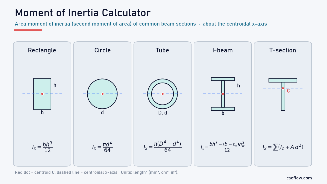
For symmetric shapes the centroidal moments of inertia have closed forms, with b the width and h the height.
Moment of Inertia of a Rectangle
$$\begin{aligned} I_x &= \frac{b\,h^3}{12} \\ I_y &= \frac{h\,b^3}{12} \end{aligned}$$
The cube is why a plank is far stiffer on edge than flat: doubling h multiplies $I_x$ by 8. About the base, $I = bh^3/3$.
Moment of Inertia of a Circle and a Hollow Tube
$$\begin{aligned} \text{solid:}\quad I &= \frac{\pi d^4}{64} \\ \text{tube:}\quad I &= \frac{\pi \left(D^4 - d^4\right)}{64} \end{aligned}$$
d is the bar diameter (or the tube’s inner diameter) and D the outer diameter. For these circular sections only, the polar moment $I_x + I_y$ ($\pi d^4/32$ or $\pi(D^4 - d^4)/32$) is also the torsion constant J.
Moment of Inertia of an I-Beam and a Hollow Rectangle
Both follow by subtracting the missing area from the outer rectangle, because the removed areas are centred on the same x-axis:
$$\begin{aligned} I_{x,\,\text{I-beam}} &= \frac{b h^3 - (b - t_w)(h - 2t_f)^3}{12} \\ I_{x,\,\text{box}} &= \frac{B H^3 - b\,h^3}{12} \end{aligned}$$
Here $t_w$ and $t_f$ are the web and flange thicknesses and b × h is the box’s inner opening. T-sections, angles and the weak axis of channels need the centroid first.
How to Calculate the Moment of Inertia of a Beam (Parallel Axis Theorem)
Any section built from simple shapes takes three steps, which the calculator also follows:
- Split the section into parts and find each part’s area $A_i$ and centroid height $y_i$.
- Locate the section centroid: $\bar{y} = \sum A_i y_i / \sum A_i$.
- Add each part’s own centroidal moment of inertia and its transfer term:
$$I_x = \sum_i \left( I_{c,i} + A_i\, d_i^{\,2} \right), \qquad d_i = y_i - \bar{y}$$
Shift only from a part’s own centroidal axis, and treat holes as negative areas. The polygon mode evaluates the integrals exactly from the corner coordinates with Green’s theorem (Steger, 1996).

Figure 1. Parallel axis theorem applied to the T-section of the worked example. The transfer terms $A\,d^2$ contribute 64% of $I_x$ = 6,171,170 mm⁴.
Worked Example: Moment of Inertia of a T-Section
A welded T-section has a 120 × 12 mm flange on a 10 mm thick web, 150 mm tall overall. Find $I_x$, the section moduli and the bending stresses for a 5 kN·m sagging moment.
Section properties · Worked example
T-section with a 120 × 12 mm flange and a 10 × 138 mm web
Heights measured from the bottom of the web; these are the calculator’s T-section defaults.
Step 1 · Parts
Split the section into two rectangles
Flange: $A_1 = 120 \times 12 = 1440$ mm², centroid at $y_1 = 144$ mm. Web: $A_2 = 10 \times 138 = 1380$ mm², centroid at $y_2 = 69$ mm.
Step 2 · Centroid
Locate the neutral axis
$$\begin{aligned} \bar{y} &= \frac{1440 \times 144 + 1380 \times 69}{1440 + 1380} \\ &= \frac{302{,}580}{2820} = 107.30\ \text{mm} \end{aligned}$$
Result: the centroid is 107.30 mm above the bottom and 42.70 mm below the top.
Step 3 · Parallel axis theorem
Add the parts
$$\begin{aligned} I_x &= \tfrac{120 \cdot 12^3}{12} + 1440\, d_1^2 \\ &\quad + \tfrac{10 \cdot 138^3}{12} + 1380\, d_2^2 \\ &= 17{,}280 + 1{,}939{,}746 \\ &\quad + 2{,}190{,}060 + 2{,}024{,}083 \\ &= 6.171 \times 10^6\ \text{mm}^4 = 617.1\ \text{cm}^4 \end{aligned}$$
Using the unrounded distances $d_1 = 144 - 107.298 = 36.702$ mm and $d_2 = 107.298 - 69 = 38.298$ mm.
Step 4 · Bending stress
Section moduli and stresses
$$\begin{aligned} S_{top} &= I_x / 42.70 = 144{,}517\ \text{mm}^3 \\ S_{bottom} &= I_x / 107.30 = 57{,}514\ \text{mm}^3 \\ \sigma_{top} &= 5 \times 10^6 / 144{,}517 = 34.6\ \text{MPa} \\ \sigma_{bottom} &= 5 \times 10^6 / 57{,}514 = 86.9\ \text{MPa} \end{aligned}$$
Result: the flange face is in compression and the web tip in tension. The web tip is 2.51 times farther from the neutral axis, so it carries 2.51 times the stress. The calculator returns the same values.
Checking the Calculator Against a Steel Table
Like most hand formulas, the calculator assumes sharp corners, while hot-rolled I-sections have root fillets between web and flanges. For an IPE 200 (h = 200, b = 100, $t_w$ = 5.6, $t_f$ = 8.5, r = 12 mm), the calculator gives $I_x$ = 1,845.6 cm⁴, 5.0% below the 1,943 cm⁴ in British Steel’s IPE datasheet.

Figure 2. IPE 200 major-axis moment of inertia: sharp-corner result, exact root-fillet correction, finite-element check and the British Steel table value ($I_y$ in Eurocode notation).
Adding the four fillets, each $r^2(1 - \pi/4)$ = 30.9 mm², gives 1,943.2 cm⁴; the finite-element tool sectionproperties returns 1,943.3 cm⁴. Area and minor axis agree too (28.48 vs 28.5 cm², 142.4 vs 142 cm⁴). Use manufacturer tables for rolled sections and the calculator for custom or welded ones.
Why Section Shape Matters
Moment of inertia rewards material far from the neutral axis. The five sections in Figure 3 have the same area, so they weigh the same per metre.

Figure 3. Five cross-sections with the same area (2,724.8 mm²). Moving material away from the neutral axis raises $I_x$ from 59.1 cm⁴ for a solid circle to 1,845.6 cm⁴ for an I-section.
The I-section’s $I_x$ is 29.8 times that of a solid square, so under the same load, span and material the square bar deflects 29.8 times more (bending deflection scales with $1/EI$; shear deformation ignored). Its section modulus, 184.6 cm³ against 23.7 cm³, makes the peak bending stress 7.8 times lower. The price is thin plates that can buckle locally, which design codes check through width-to-thickness limits.
Common Mistakes
- Using $I_x + I_y$ as the torsion constant. This equals J only for circular sections. For the IPE 200, $I_x + I_y$ ≈ 2,086 cm⁴, while the tabulated torsion constant is 6.92 cm⁴, about 300 times smaller.
- Mixing up axes. $I_x$ here is $I_y$ in Eurocode tables.
- Unit slips. A factor of 10 in length becomes 10⁴ in $I$.
- Ignoring $I_{xy}$. For an angle, a vertical load also bends the section sideways unless it is restrained. Use $I_1$, $I_2$ and $\theta_p$ (19.95° for the default L 100 × 60 × 8) or a biaxial bending check.
Limitations of the Calculator
- Idealised geometry: no root fillets or corner radii, and one polygon outline without holes.
- One homogeneous material; steel–concrete and other composite beams need a transformed section.
- Elastic properties only: no plastic modulus, warping constant or shear centre, and J only for circular sections.
Conclusion
The area moment of inertia drives both beam stiffness and bending stress. Use the calculator for idealised sections, the parallel axis theorem to check by hand, and manufacturer tables for rolled sections. Beam elements in FEA use the same properties (A, I and J); see our finite element method guide and 3D Mohr’s circle calculator.
FAQ: Moment of Inertia Calculator
How do you calculate the moment of inertia of a beam?
Split the cross-section into simple parts, find the section centroid, then add each part’s centroidal moment of inertia plus its area times the squared distance to the centroid (parallel axis theorem). For a solid rectangle this reduces to I = bh³/12. The calculator above does this exactly for ten shapes.
What is the moment of inertia of a rectangle?
About its horizontal centroidal axis, a rectangle of width b and height h has I = bh³/12; about the vertical centroidal axis it is hb³/12, and about its base bh³/3. A 100 mm wide, 200 mm tall rectangle has Ix = 6.67 × 10⁷ mm⁴ (6,667 cm⁴).
How do you find the moment of inertia of an I-beam?
For a symmetric I-beam, subtract the two empty rectangles beside the web from the outer rectangle: Ix = [bh³ − (b − tw)(h − 2tf)³]/12. For an IPE 200 this gives 1,845.6 cm⁴ with sharp corners; the published 1,943 cm⁴ also includes the root fillets.
What are the units of the area moment of inertia?
Length to the fourth power: mm⁴, cm⁴, m⁴ or in⁴. Conversions scale with the fourth power of the length factor, so 1 cm⁴ = 10,000 mm⁴ and 1 in⁴ = 416,231 mm⁴. The mass moment of inertia uses kg·m².
What is the difference between moment of inertia and section modulus?
The moment of inertia I describes bending stiffness and controls deflection. The section modulus S = I/c divides I by the distance c from the neutral axis to the extreme fibre and controls the maximum elastic bending stress, σ = M/S. Unsymmetric sections such as T-sections have two section moduli, one per extreme fibre.
References (clickable):
- Gere, J. M., & Goodno, B. J. (2018). Mechanics of Materials (9th ed.). Cengage Learning.
- Young, W. C., Budynas, R. G., & Sadegh, A. M. (2012). Roark’s Formulas for Stress and Strain (8th ed.). McGraw-Hill.
- Hibbeler, R. C. (2016). Engineering Mechanics: Statics (14th ed.). Pearson.
- British Steel (2026). IPE sections: dimensions and properties (datasheet).
- CEN (2005). EN 1993-1-1, Eurocode 3: Design of steel structures, Part 1-1: General rules and rules for buildings.
- Steger, C. (1996). On the calculation of arbitrary moments of polygons. Technical Report FGBV-96-05, Technische Universität München.
- van Leeuwen, R. sectionproperties: a Python package for the analysis of arbitrary cross-sections using the finite element method.
